Industrial software enables real-time data and control for hydraulic gripper arms
Our challenge was creating an intuitive, reliable system to deploy, position and stow hydraulic gripper arms used in guiding steel monopiles for offshore wind farm construction.
By developing integrated control that uses a CompactRIO and LabView software from National Instruments (NI), the system performs real-time data acquisition, monitoring and a position-control algorithm.
Wind power
The construction of offshore wind farms involves driving large-diameter, 65-m-long steel monopiles into the seabed. Specialized jack-up vessels host large cranes that carry and lower the piles into the water before hammering them into the seabed at depths of up to 40 m.
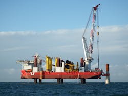
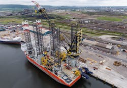
Figure 2: Houlder developed the gripper-arm concept and mechanical design, with the support and involvement of MPIC and MPI Offshore vessel management, for the offshore vessel MPI Discovery.
The piles then serve as the foundation for installing wind-turbine towers. Keeping the pile vertical while driving it with an hydraulic hammer poses a serious challenge, especially in the presence of large currents and waves.
Once stationed, correcting monopile positioning inaccuracies is extremely costly and requires full removal and redriving. Day rates for chartering installation vessels are a very significant cost to the industry, so reducing delay is a key driver of technical improvement.
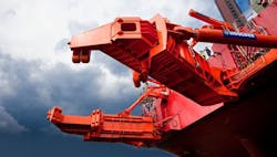
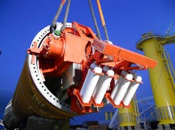
The solution for this problem is a pile guidance tool—pile gripper arms (PGA) (Figure 1). The pile gripper arm holds and maintains the pile’s vertical position while it is driven. Houlder developed the gripper-arm concept and mechanical design, with the support and involvement of MPIC and MPI Offshore vessel management, for the offshore vessel MPI Discovery (Figure 2).
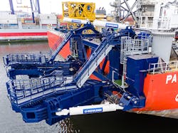
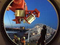
Figure 3: The hydraulically driven gripper arms aided the handling of large monopiles that were up to 700 tons in weight, 75 m long and 7 m in diameter.
Following the successful implementation of a hydraulic, motion-compensated turbine access system, Industrial Systems and Control (ISC) was involved from the outset of this project.
Initially, we used dynamic simulations to investigate the effect of using feedback control in parallel with hydraulic counterbalance valves, which are a potential source of control issues, and to assess the achievable positional accuracy.
We used NI LabView software and the LabView Real-Time Module, the LabView FPGA Module, the LabView MathScript RT Module and the LabView Touch Panel Module to implement control software. Before connecting to the actual system, we thoroughly tested the algorithm functionality using a detailed software emulator.
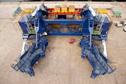
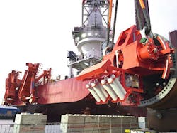
Figure 4: Three main hydraulic cylinders actuated each gripper arm.
Next, we performed factory commissioning and testing using the available parts of the real system, while simulating pieces that were not present and exploring the performance of the individual cylinder control loops, as well as the overall x-y motion.
Due to the large size of the mechanical components, we could not fully assemble the gripper arms in the factory, so we virtually displayed expected overall behavior via the emulator. Installation and testing on the vessel followed, with successful sea trials held shortly after that.
Pile gripper arms
The hydraulically driven gripper arms aided the handling of large monopiles that were up to 700 tons in weight, 75 m long and 7 m in diameter (Figure 3).
Figure 5: Seventy-ton arms typically maneuver a 630-ton pile, which meant we could only fully test the final control system once fully installed on the vessel.
Three main hydraulic cylinders actuated each gripper arm (Figure 4). One cylinder raised and lowered from the stowage (vertical) position, and the other two provided motion in the x-y plane. We could individually or synchronously steer the arms to adjust the vertical inclination of the pile.
It is critical that the control system prevents the gripper jaws from crushing the pile, so a preset minimum gap constraint must be observed at all times. The additional challenge lies in the sheer physical size of the system. Seventy-ton arms typically maneuver a 630-ton pile, which meant we could only fully test the final control system once fully installed on the vessel (Figure 5).
Control system components
We developed the gripper arm control system (GACS) to ensure reliable deployment, stowage and positioning of the gripper arms in the horizontal plane via a joystick located in the operator’s chest pack.
Figure 6: Constraint-handling logic maintained appropriate behavior at the edge of the operating envelope, facilitated arm retraction for stowage and limited permissible jaw diameter to prevent pile damage.
We used LabView and NI CompactRIO hardware to develop the complete control system for the gripper arm. We designed an algorithm combining the forward and inverse kinematics of both gripper jaws to compute the hydraulic cylinder lengths required to move the arm in a desired direction. A simple, proportional-integral control minimized cylinder position errors. Constraint-handling logic maintained appropriate behavior at the edge of the operating envelope, facilitated arm retraction for stowage and limited permissible jaw diameter to prevent pile damage (Figure 6).
Operational logic, monitoring and fault actions are also executed on the CompactRIO and accessed through a touch panel computer (TPC) with a joystick and a set of buttons/LEDs integrated into the operator’s chest pack. The NI TPC running Windows XP was used to provide the GACS operator interface, which was also built using LabView.
The CompactRIO embedded controller was equipped with numerous input/output (I/O) modules to interface with the sensors, actuators and the operator chest pack. The CompactRIO controller was approved by Det Norske Veritas (DNV) for safety, EMC and environmental rules for marine environments.
Figure 7: An emulator was developed to extensively test the operating logic and fault response before the real factory or vessel trials.
The structure of the GACS software included the main real-time (RT) application, a field-programmable gate array (FPGA) program including a watchdog, the HMI software running on the TPC and the PC-based emulator used during development and commissioning only.
We developed the emulator to extensively test the operating logic and fault response before the real factory or vessel trials (Figure 7). The emulator ran on a computer connected to the CompactRIO system via Ethernet, and network-published shared variables were defined to exchange data between the emulator and the main application. In addition, the emulator replaced any component that was not physically present during factory test.
Control system functions
The GACS handled the deployment and stowage of the arms using two lifting hydraulic actuators (Figure 8). Two pairs of hydraulic cylinders performed the x-y position control, which the operator guided using the chest-pack joystick. The GACS software included the following features.
Figure 8: The GACS handled the deployment and stowage of the arms using two lifting hydraulic actuators.
Inverse kinematics: calculates the cylinder lengths required to move the gripper arms to a given position in the horizontal plane. We initially implemented this using MathScript nodes; however, we subsequently recoded using native LabView to optimize execution speed.
Forward kinematics: monitored the individual and relative gripper arm positions to handle the system constraints—envelope and pile gap—and also for display on the TPC.
RT control: interpreted operator joystick movements as the commanded direction and arm movement speed. This speed demand was internally converted to the x-y position setpoints using inverse kinematics and the current x-y positions of the arms. The setpoints were rate-limited and then passed through inverse kinematics to convert into the corresponding cylinder lengths, taking into account their minimum and maximum limits. Finally, the individual cylinder length dynamic controllers—PID feedback—computed the control signals to drive the corresponding hydraulic servo valves. Individual cylinder controllers also featured feed-forward paths to improve tracking performance, which also allowed different gains for cylinder extension and retraction to be applied (Figure 9).
Figure 9: Individual cylinder controllers featured feed-forward paths to improve tracking performance
Operational logic: implemented in the LabView state machine code architecture, which made different modes and submodes of operation—initialization, inactive, deploy/stow, single arm, synchronous—possible (Figure 10).
Monitoring: extensive monitoring of analog I/O, digital I/O and internal states and calculations ensured faults were trapped and received a quick and appropriate response, whether just a warning to the operator or a controller initiated emergency stop. An external safety relay circuit responded to both external emergency-stop buttons and GACS-initiated faults.
Watchdog timer: automatically initiated an emergency stop, should the embedded control software become unresponsive, which we implemented using the FPGA on the CompactRIO controller for high-integrity operation. A second watchdog monitored the network connection between the CompactRIO system and the TPC.
Figure 10: Operational logic was implemented in the state machine code architecture, which made different modes and submodes of operation possible.
Operator interface: built as a standalone LabView executable running on the TPC integrated with a joystick and a variety of buttons/LEDs. The TCP communicated with the CompactRIO control software through shared variables via Ethernet.
Sea trial results
As soon as the gripper arm and its software were installed and commissioned on the MPI Discovery, it set out for the Humber Gateway Offshore Wind Farm to install four monopiles and transition pieces—the visible, yellow base of offshore wind turbines (Figure 11). This wind farm is located 8 km from the coast near Grimsby in the United Kingdom, in water depths of up to 18 m. The site consisted of 73 turbines when it was completed.
ISC engineers were present for the successful installation of the first two monopiles, which require the gripper arm working to position and keep them vertical for the lengthy piling operation, which lasts several hours. The system worked well and matched expectations from the factory testing, with just a few items requiring fine-tuning on the day.
Figure 11: As soon as the gripper arm and its software were installed and commissioned on the MPI Discovery, it set out for the Humber Gateway Offshore Wind Farm.
Fast development, flexible interface
The control-system development was very successful. We moved from a blank sheet of paper to implementation to factory testing and finally successful sea trails in just a few months.
While discussing the successful implementation of the gripper-arm system, Frederic Perdrix, chief technical officer at Houlder, said, “The result combines heavy-duty structural, mechanical and hydraulic engineering with precision control.”
The combination of LabView and CompactRIO delivered all the computational power required for our low-level control and kinematic calculations, as well as the determinism and reliability required for our safety-critical operational logic. The small size and low-power nature of the CompactRIO and TPC screens suit the marine environment and provided a very flexible interface to the I/O required for this application.
About the author
Pawel Majecki is senior technical consultant at Industrial Systems and Control in Glasgow, United Kingdom. Contact him at [email protected].
About the Author
Pawel Majecki
Industrial Systems and Control

Leaders relevant to this article:
