A Control Design reader writes: We manufacture OEM and custom machines—discrete manufacturing—and are looking for ways to reduce integration time and overall cost. Specifically, we're looking at I/O termination methods. We want to move away from wire or cable from the field device to the enclosure terminal strip. We are looking to reduce the large bundles of wire and terminating our I/O at the edge, but technology and reliability concerns are part of the discussion. There are many network, protocol and hardware choices, so what are our options, and how can we be more efficient with I/O termination?
ANSWERS
Follow protocol
Reducing wiring costs was the problem industrial networks were developed to address. Unless you have very specific application requirements, for example, such as those needed for high-speed motion control, most Industrial Ethernet networks will be able to handle your machine cycle times.
There are a variety of industrial Ethernets from which to choose, and typically there’s not one “best” solution. The network “religion wars” are more about the ability of integrated solution providers to have cohesive, well-implemented product offerings across their entire product lines than one network protocol being “better” than another.
So, if you have a preferred vendor, then go with the vendor’s native network protocol. But if you want to use devices from various vendors, then use the network that they all have in common. Preference should be given to the network protocol supported by your PLC controller, since the controller’s native network is usually easier to implement than a competitive network.
In summary, industrial Ethernet should accommodate most, if not all, of your application requirements. And, as for your network protocol choice, you can accommodate different protocols, as needed, by using gateways and converters. This allows you to select best-in-class components while reducing integration time and costs.
PHIL MARSHALL / CEO / Hilscher North America
Choose for the user
When it comes to choosing an I/O termination method, there are a few things to consider. First, consider the size of your machine. Small skidded machines may not have a lot of benefit for distributed I/O since the wire runs are short, but you can still optimize to reduce integration time. Use easy-operating, tool-free levers on your terminal blocks for field terminals or use IP67 sensor and actuator connectors. They are easy to mount and connect eight to 10 local I/O points and then have a single cable to route back to your control cabinet.
For systems that are physically large, distributed I/O is very beneficial. In some cases users can use an HMI and PLC all in one and use a fieldbus coupler to monitor and control remote distributed I/O. There are lots of good options for fieldbuses; however, Ethernet-based devices are the trend.
There is a wide variety of protocols including Modbus TCP/UDP, EtherNet/IP, EtherCAT and Profinet. A lot of times the choice of the fieldbus is dependent on the dominant one in the end user’s plant. It can be easier on the maintenance staff to work with the fieldbus they are used to. Modbus TCP/UDP has been around for decades and is readily available on field devices like drives or flow meters.
EtherCAT is newest of the protocols and offers a lot of advantages regarding speed and diagnostics. EtherCAT is growing at a high rate around the word. All of these Ethernet networks provide reliable communications in the industrial environment. When making a choice of which one to use, base your choice on the type of application and user experience.
CHARLIE NORZ / automation product manager / Wago
Multi-port interconnection
Machine builders/OEMs often need to wire multiple sensors and other discrete devices back to a control panel. One option is Remote I/O with each input converted to a digital communication signal, but this tends to be expensive and limits use to controllers capable of receiving and interpreting the digital signal. A less expensive solution is to simply take a group of input signals and combine them into a single cable using junction blocks designed specifically for this purpose.
Multi-port interconnection junction blocks provide a simple and effective way to organize machine wiring for a variety of machine control applications, such as packaging equipment and conveying systems. These systems typically have many I/O points, such as sensors or solenoid-operated valves, consolidated in one location. These devices are usually hardwired to a junction box or separately wired back to the main control cabinet. Multi-port junction blocks provide a more efficient and cost-effective solution: one main control cable is run back to the main control cabinet, so the cost associated with errors in wiring, rewiring and I/O replacement is greatly reduced. The designer can choose from a variety of circuit configurations with industry standard M12-style connections; in port configurations of four-, six- and eight-pole; and with a choice of one or two I/O per port.
JIM KREBS / engineer / AutomationDirect
Split systems
ANDY WOODS / chief operating officer / icotek North America
Don’t fight the PLC battle
While many industrial network protocols are indeed available, there are two device-level communication methodologies that lend themselves to reduced wiring: AS-interface and IO-Link. Each has its own advantages in terms of data throughput, speed and capability, and they are complementary technologies that can offer different benefits for the OEM. Both are PLC-independent, so there’s no need to fight the PLC battle.
AS-interface, a low-level industrial network with more than 36 million installed devices across the globe, is supported by more than 350 device vendors. With network distances of up to 500 meters and the ability to accommodate 248 inputs and 248 outputs on a single, two-wire cable, it’s common to realize up to 90% fewer termination points in large networks. Savings of up to 75% in installation costs alone are common, and other savings for the OEM include fewer errors, less labeling, less I/O cards, smaller cabinets, less cable, cable tray and conduit, and easier installation and commissioning.
IO-Link is a point-to-point communication methodology, originally developed as a means of connecting sensors to controllers. With a 20-meter limit on the cable length between master and device, IO-Link is best suited for use where the controller is in close proximity to the machine-mounted sensor devices. A unique solution inside the cabinet can reduce panel wiring time and hardware cost. By utilizing IO-Link on motor starters inside the control cabinet, installation time can be reduced by at least 50%, and overall cost reductions of greater than 25% are common.
GLENN SYMONDS / product marketing manager / Siemens Industry, Smart Infrastructure—Control Products
Next generation
Despite the variety of features, the installation is very simple and fast; modules are hooked up onto the cable via piercing technology. Special needles pierce a small hole through the isolation and contact the wires without damaging them. You can change the position of the module just by taking it off and moving it to another position. The topology of your network is completely free and can follow the shape of your machine—even networks with 1,000 meters in length can be realized.
For cases where an additional auxiliary power supply is inevitable, an additional cable—black ASi profile cable—can be used to transfer the energy. Just like the yellow ASi cable, it is contacted via piercing technology, and it can use the same cable duct, as well.
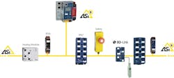
Figure 1: The simplest way of reducing the wiring costs for your I/O termination is to reduce the number of wires to one single cable.
AS-Interface is a bus system designed for field devices that is capable of transferring standard and safety signals, up to PLe/SIL 3/Cat. 4, as well as energy on one single, two-conductor electrical cable—the ASi cable. With it, usual cable trees can be replaced.
ASi-5—the latest innovation stage of AS-Interface—is able to transmit large data volumes, up to 384 bits, within very short cycle times, 1.27 ms, which makes it an alternative for higher-level fieldbuses, such as Ethernet/IP. Moreover, power and data are transmitted over the same cable, so that in many cases there is no need for additional power supplies in the field.
The connection to the PLC is realized over a gateway, which speaks the matching protocol of your PLC. When you have to change the PLC, you just change the gateway, and the rest of the installation stays the same (Figure 2).
Figure 2: The connection to the PLC is realized over a gateway, which speaks the matching protocol of your PLC.
The different ASi modules offer you the right connection for every signal; digital I/Os, analog signals and even IO-Link sensors can easily be made bus-capable in the blink of an eye. The key lies in the flat, yellow ASi cable.
DENYS SERHA / field application engineer / Bihl+Wiedemann
I/O communication and power
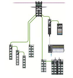
Figure 3: An I/O system can utilize single-cable connectivity to transfer I/O communication and power between your choice of different, configurable I/O modules.
Typically, OEMs can expect to save up to 40% in wiring costs with an IP67 distributed I/O installation as compared to traditional discrete wiring methods. This is before they realize the savings in setup costs or take full advantage of diagnostic capabilities in the system. You will find a lot of technologies to look at when you start to consider wiring methods.
AARON HENRY / VP strategic development / Murrelektronik
Get remote
Remote I/O systems provide the best option for combining conventional I/O signals—AI, AO, DI, and DO—with modern communication protocols such as Profibus DP, Profinet and Modbus RTU/TCP. These systems convert the standard analog and digital signals into a single communication protocol used by the manufacturing facility.
One benefit that a remote I/O system brings is the ability to reduce the wiring back to the control room. In a point-to-point installation, huge amounts of wiring are needed to and from the field device and the control room, which requires long cable lengths, engineering design and costly installation time. A remote I/O system is typically installed as close to the field device as possible. This allows for a maximum reduction of wiring, since the installation has a single communication cable/bus running back to the control room, effectively reducing your wiring costs by nearly 50% (Figure 4).
Figure 4: A remote I/O system is typically installed as close to the field device as possible.
A remote I/O system’s bus communication also allows you to reduce the number of DCS I/O cards, saving money and also cabinet space in the control room. In a point-to-point installation, individual I/O cards are required for each signal type. Depending on the instrument count, this could be a substantial quantity of I/O cards. In a bus-communication architecture, the DCS control cards would be drastically reduced, because only communication cards for the specific bus, such as Profinet, would be required.
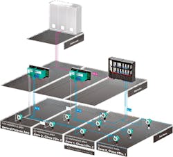
Most remote I/O systems are based on a backplane structure, with slots for a communication module, I/O modules and power supplies. The high-density I/O modules allow for the maximum number of modules to be placed inside a single cabinet. Many remote I/O systems can be integrated in both general purpose and hazardous location installations (Figure 5).
Figure 5: Many remote I/O systems can be integrated in both general purpose and hazardous location installations.
ALBINO SALAZAR / technical support supervisor / Pepperl+Fuchs
Network architecture
It seems to me that a network I/O system is something you should look into. Going to a network I/O system will allow you to reduce field cabling from many individual wires to as little as one network cable. This can reduce the cost of building the enclosure and makes it much easier to seal the enclosure from environmental issues, such as water and dust.
Over the years a number of network technologies have come into general use, and, due to advances in technology, some have been replaced. For some very high-speed applications, putting the I/O on a network could have caused some latency issues, but the recent high-speed networks of up to 100 GB are making these issues rare exceptions.
The current frontrunners in industrial networks are almost all Ethernet-based. EtherCAT, Ethernet/IP and Profinet as examples are all Ethernet-based. Most, including these three, are in the public domain, so manufacturers of automation equipment can enable their products with them. Each has its own features that may make it more suitable for an application. For example, EtherCAT is highly regarded for motion applications. In all cases an overlaying protocol is added to increase determinism. Reliability is very high with these protocols. On the data side there are checksums and retries to ensure data transfer.
On the hardware side, IP20 or IP67 blocks are available for most environmentals. Most terminations with these protocols are with an RJ45 connector and jack. So it is very common and easy to terminate or purchase pre-made cables. In IP67 environments, typically M12 connectors are used for liquid and dust tight operation. I/O terminations are sometimes dictated by the environment.
Specialized networks are also being used at the sensor and I/O level. One example is IO-Link. IO-Link was designed as an optimized protocol for sensors but is now finding use in more advanced devices. Data integrity is very high. Here again you can find connectivity for IP20 applications with cage clamp or screw terminal or M12 connectors for liquid and dust tight operation (Figure 6).
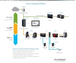
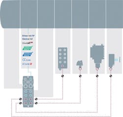
Figure 6: A typical modern network architecture can have EtherNet/IP at the top level for the high data transfer rates and determinism; EtherCAT for its determinism and performance with motion and I/O; and IO-Link at the sensor level for highest speed with smaller data packets found in sensors.
A typical modern network architecture can have EtherNet/IP at the top level for the high data transfer rates and determinism; EtherCAT for its determinism and performance with motion and I/O; and IO-Link at the sensor level for highest speed with smaller data packets found in sensors.
There are more than just these networks out there. If you start your design with the most modern and capable networks, you can ensure years of reliable operation and the lowest total cost of ownership.
CLARK KROMENAKER / product manager—HMI, IPC, controllers, software / Omron Automation Americas
I/O architectures
For the longest time I/O termination was the only cost-effective way for machine builds. Over the years, many technologies have been developed to increase the productivity for machine builders. We call it the evolution of I/O architectures.
The wiring and terminations are the first generation of the I/O integration philosophy that relies heavily on centralized controls architectures with laborious and time-consuming wiring. Terminating each wire is a six-step process that includes routing, cutting, stripping, ferruling, labeling and terminating. Typically, it takes about 7-10 minutes per wire for experts. So, if you have 100 terminations it would take up to about 12 hours of time, equating to about $700-$1,000 of labor cost.
All of this hard work is also accompanied by absolutely no diagnostics. With human error probability stats at about 10-15%, you are looking at additional cost of debugging wiring errors and re-works. All these are non-value-added activities.
The second generation of I/O architectures adds passive junction boxes. These help to shorten the cable runs from the sensors to the junction box, but do not reduce any terminations or offer any diagnostics. So, the trade-off with the passive junction box strategy is you may be able to reduce a little on labor time, but it provides no benefits on diagnostics or error preventions.
The third philosophy in I/O architectures is distributed or remote I/O stations using fieldbus or network architecture. There are two choices here: (1) using remote termination boxes or (2) using remote I/O blocks with direct connections.
The first choice helps with distributing your terminations closer to the sensors but does not help reduce any terminations. So, it helps with shorter cable runs and probably provides a little more diagnostics but adds the cost of remote termination control panels. The second choice, however, offers shorter cable runs, onboard diagnostics of short circuits or overcurrent, drastically reduces terminations. Just as importantly, it considerably reduces the need for debugging, which reduces overall labor costs.
But the limitation here is that typically a distributed network block can host 16 inputs or outputs or four to eight analog points, or some mix thereof.
So, when you need the 17th input or output, you need to add another I/O block on the network, if you need one additional analog input or output, you need a different block, and so on. Basically, you are dumping the I/O slices from the cabinet out on the machine connected with network nodes. So, the marginal cost of update is very high.
The fourth or the latest generation of I/O architecture is based on IO-Link technology(Figure 7). This technology has been out for more than a decade, and it is gaining very fast acceptance in the market. It is also the technology most useful for Industry 4.0 or Industrial Internet of Things.
Figure 7: IO-Link is a standard interface. You use the same standard cable across the board for integrating discrete I/O; analog I/O; smart devices and sensors; and specialty devices such as RFID and vision.
With each IO-Link master block, you typically get up to eight IO-Link ports, and each port can host a variety of I/O. The I/O devices or I/O hubs are child nodes that spawn out of the IO-Link master to capture discrete I/O, analog I/O, smart devices such as RFID, smart sensors such as pressure, color, ultrasonic, laser distance or even transducers and encoders.
Now, with this technology, one IO-Link master could host up to 240 I/O points with IO-Link I/O hubs, or up to 64 channels of analog I/O or eight IO-Link smart devices or any combination thereof.
There are more and more manufacturers introducing new devices that would go on IO-Link. There is an influx of smart devices on IO-Link, such as valve manifolds, grippers, vacuum generators, stack lights and RFID systems. Since IO-Link is a data communication and not signal transmission, each IO-Link device offers considerable amounts of diagnostics. The IO-Link devices could be configured to provide events in alarming situations for ease of maintenance and troubleshooting. The best part is you could use standard sensor cables that you are using today throughout the architecture except the IO-Link master that sits on the network. With IP67-rated IO-Link masters, you could use molded quick-connect cables to avoid any miswiring.
In short, with IO-Link technology, you eliminate or reduce your wiring and terminations drastically, thus reducing your time to build machines, make your machines smarter with tons of diagnostics abilities, adaptable to changing technologies for sensors and smart devices, modular with use of I/O hubs, and standardize on connectivity across the machine or the plant.
SHISHIR REGE / marketing manager / Balluff
Away from parallel wiring
In today’s manufacturing world, automation has become king; and, with that, companies are constantly looking for ways to do it better, faster and cheaper.
Massive bundles of wire have always been a thorn in the side of process improvement and general organization. Fortunately, there are many technology options available to eliminate this hassle, so that you can reduce your integration time and improve your future productivity.
The two options I would suggest are: (1) distributed modular I/O and (2) wireless technology, depending on how much of a transition you are willing to make.
The first step is to look at your control system and determine which protocol you can use. Whether it is Ethernet/IP, Profinet or Modbus TCP, you need to decide if you are always going to use the same controller, or will you vary between manufacturers. If you think you might switch, you will want to use a brand that supports all of the common protocols.
In terms of distributed modular I/O, this solution lets you terminate outside of the cabinet and at your machine, while reducing the number of individual wires to a fraction of what they were before, often bringing you down to just a few cables.
It’s also always important to take a look at the connection technology offered by different brands. For example, push-in tool-free and quick-connect connections are major timesavers without sacrificing reliability. In most instances, you see large bundles of wire running back to the panel, which not only is very tedious to install, but also creates organizational and space concerns and adds time-consuming maintenance.
Distributed modular I/O allows you to terminate your I/O where you need it and eliminates many bundles of wire. Also, if you have a long distance to span, you can use an IP67 direct machine-mount option. While not the most cost-effective option, these options are still less expensive than additional intermediate cabinets. Both of these options allow you to collect data at a single point and communicate over an industrial network. In terms of technology, communications over industrial Ethernet networks have come a long way, and, now, they are a reliable solution to help you move away from parallel wiring.
Depending on how invested you are in cutting the cord, so to speak, wireless I/O can be an intriguing solution. While they can be a little more of a capital investment up front, they often pay for themselves in terms of installation cost savings, versatility, ease of use and placement and reduced maintenance costs. One of the main issues with wireless technology is that it must match the durability and reliability of a traditional cable connection. For this reason, it is important to select a brand that offers the correct ingress protection and area classification ratings for your needs. It is also important to select a technology that transmits I/O signals, as well as serial data, and is capable of being implemented in point-to-point connections or more complex networks. These attributes will give you the freedom to transmit I/O to I/O, I/O to serial or serial to serial. Another attractive option is industrial Bluetooth. Industrial Bluetooth modules can replace Ethernet, or other cables, with a reliable wireless connection. Bluetooth is particularly useful for mobile applications, such as cobots or robots, eliminating costly cable runs.
Implementation of one or both of these solutions will greatly increase your termination efficiency. However, with so many options and brands available today, it is important to select one that has the most versatility and features that match your current, as well as future, needs.
WILL MORRIS / product portfolio manager / Allied Electronics & Automation
Distributed I/O and fieldbus
The use of distributed I/O is becoming more prevalent with several options when it comes to protocols.
By placing distributed I/O blocks on the machine with a fieldbus system, you only need to run the power and fieldbus cable back to the PLC.
We like to use M12 connector blocks that allow short cabling to the sensors. If a cable is damaged, you can quickly change it out without pulling wires back to the PLC enclosure.
One manufacturer we like to use offers a fieldbus block that allows changing out the bus coupler instead of the whole system. This makes the installation independent of the controls and fieldbus, allowing OEMs to adapt to an end user’s PLC and fieldbus specification.
When using a fieldbus protocol, always look at how it integrates into your PLC. Many manufactures have developed electronic data sheet (EDS) files that allow products to easily be identified and commissioned in your control system.
Also, pay attention to the environment that the I/O blocks and cabling will be installed in and select the proper IP rating.
LINDSEY KIELMEYER / marketing coordinator / Martin Control Systems, Plain City, Ohio / member, Control System Integrators Association
No cabinet
First, it reduces the size and cost of the control cabinet. Additionally, using a network communication to control the components outside the cabinet reduces the number of cables routing out of the cabinet. This reduces time required to wire into terminal blocks and reduces the length of cable runs to the components.
Second, it reduces wiring errors and time by using M-style connectors for network communication and power. These types of connectors are available as cordsets (connectors at each end) and patchcords (connector at one end, leads on the other). They are also available as field-attachable for quick assembly. Additionally, they are keyed according to functionality to help prevent wiring errors. The combination of a network communication with M-style connectors is commonly used and helps to reduce the concern of machine reliability.
Third, it reduces wiring runs by mounting the components closer to the end devices.
With this design, a machine can be modular because a portion can be disconnected quickly for shipping and then put together just as quickly at the customer site, resulting in an overall reduction in installation costs.
As an alternative to using an on-machine solution, I/O can also be mounted closer to input/output devices or motors, reducing wiring runs. This distributed I/O option offers standard and safety modules with field-ready terminal blocks and reduces the need for separate I/O terminations. I/O adapters also allow for various network communication options, such as fiberoptic support.
TOK KIANG LING / global product manager / Rockwell Automation
EtherCAT solutions
The system allows machine builders to design custom circuit boards for the necessary I/Os and standard connectors, which offers significant advantages and ROI for series machine production. Prefabricated cables or coded plug connectors enable the connection of standard cables to the board in a machine control system. The terminals are also about half the size of their standard DIN rail-mounted I/O counterparts, and this leads to dramatic reductions in equipment footprint, enabling installation of I/O inside the machine to reduce the size and number of electrical cabinets.
Designed for harsh production environments, rugged EtherCAT modules come with an IP67 protection rating, including plastic and zinc die-cast models. There are also stainless steel IP69K versions that enable flexible mounting outside control cabinets in food, beverage and pharmaceutical applications, for example. EtherCAT terminals can save valuable space by installing the I/O system directly onto the machine. The potted plastic EtherCAT modules are also available with One Cable Automation (OCA) via EtherCAT P, which delivers power and communication with a single cable and connects easily to the devices using standard M8 or M12 connectors. The resulting distributed I/O architectures help machine builders reduce cabling and footprint along with time-intensive point-to-point wiring.
On top of standard digital/analog inputs/outputs, both the circuit board-pluggable and machine-mountable I/O offer high-density 16-channel options, motion control terminals that support one-cable technology for power and feedback and even TÜV-certified machine safety with I/O in yellow housings. This range ensures practically all I/O requirements for discrete manufacturing applications are available in the pluggable form factor but can also connect directly to standard, DIN rail-mountable I/O if specific couplers or other extensions are needed. All of these solutions harness the proven EtherCAT protocol, an open industrial Ethernet solution that boasts the ability to support up to 65,535 devices on a single network. Built-in LED lights display EtherCAT diagnostics directly on the hardware as they do on standard terminals. These factors make each solution an even more compelling choice to reduce wiring in production machines.
SREE SWARNA GUTTA / I/O application specialist / Beckhoff Automation
Evolve into fieldbus
This is a great time to be evolving your machine-controls design into a fieldbus solution. There have been tremendous improvements in industrial network technology. The large automotive manufacturers have led the way in driving common network specifications and implementing quick-disconnect (QD) I/O and power solutions. The necessity of shorter project timelines and quicker startups and the scarcity of "friendly" electricians have helped to increase the pace of the implementation.
Automation manufacturers have responded with plug-and-play solutions for the two dominant fieldbuses—Ethernet/IP and Profinet. There are other options here, but nowhere near the number of solutions and reliability between those two. Your PLC manufacturer’s country of origin will dictate your decision between the two.
On top of that, your distributor, also known as your solution partner, should be able to help with the design choices and target the low-hanging fruit on your machine.
An evaluation of the required field I/O, type, density and whatever flexibility required will help refine your choices. The solution partner will also be able to provide demo products and working solutions; the wheel has already been designed, no need to start from scratch. This should help to reduce any extra burden on your controls staff; they have enough other opportunities making the machine work.
TOM LANDON / automation manager / Motion Industries Electrical Specialties Group
Mike Bacidore is the editor in chief for Control Design magazine. He is an award-winning columnist, earning a Gold Regional Award and a Silver National Award from the American Society of Business Publication Editors. Email him at [email protected].
Control Design Newsletters
About the Author
Mike Bacidore
Editor in Chief
Mike Bacidore is chief editor of Control Design and has been an integral part of the Endeavor Business Media editorial team since 2007. Previously, he was editorial director at Hughes Communications and a portfolio manager of the human resources and labor law areas at Wolters Kluwer. Bacidore holds a BA from the University of Illinois and an MBA from Lake Forest Graduate School of Management. He is an award-winning columnist, earning multiple regional and national awards from the American Society of Business Publication Editors. He may be reached at [email protected]

Leaders relevant to this article:


