How laser control systems with modular technology affect motion and gantry systems

Laser processing puts additional hardware requirements onto an automation system, and the system designer needs to be aware of the input and output needs of connecting a laser to a controller. In theory, every time a system integrator designs a new system with advanced laser control abilities, the system integrator must take the input/output capability of the master controller or the master drive unit into consideration.
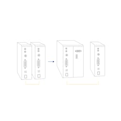
This is frustrating because the focus shifts from the servo performance required to the laser connection functionality. Typically, the machine builder has to literally rebuild the entire control system to take account of these additional requirements. This may involve replacing the first drive unit with a physically larger, much more complex and more expensive drive that combines such capabilities (Figure 1). This can have a significant impact on cost, including time for redesigning the system, additional hardware, stock of spare parts and larger electrical cabinets. Modular design
A laser control interface (LCI) introduces a way to construct motion systems, based on the EtherCAT industrial network. It does not rely on encoder data and allows drives to select specified axis requirements. This approach offers system integrators, particularly those who are new to the field, a way to expand capabilities when it comes to laser control and gives them the flexibility to add high-performance, multi-axis capabilities only when they are needed, greatly simplifying the system architecture of the drives.
Sharper performance
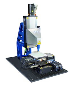
Motion systems combined with well-designed mechanical platforms that take into account the demands of laser processing allow the user to simply add laser control using the LCI module to fire along a highly accurate path, as the controller dynamically corrects disturbances and vibrations that occur in real time, ensuring minimal following errors (Figure 3). The ability to use any type of feedback is advantageous from a system integrator’s point of view because it offers the potential to mix axes with or without encoder data, combine incremental and absolute encoders or incorporate kinematic systems that cannot interpret direct output from encoders. This means that a system that uses the right technology to solve the problem can be created.
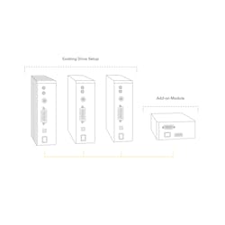
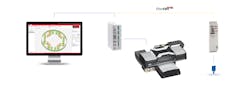
In contrast, the modular concept adds PEG to an entire drive system using EtherCAT, integrated with an Ethernet Cat. 5e cable, taking the individual path information directly from each motion device on the EtherCAT bus and linking the positional information from multiple axes to a single PEG output (Figure 4). This data is then used to generate laser control events along the combined vector path, controlling the laser attached to the system. No feedback, absolute encoders and kinematic transformation Using stepper-motor-driven stages for laser control must be undertaken with caution. Open-loop positioning does not provide information when a motor has lost position due to a potential fault, but it does open up the method for lower cost and less demanding motion applications. In addition, there are certain situations where absolute encoders are ideal because they do not require referencing at machine power- up. This can help avoid collisions of stages or parts with obstacles in the machine layout, allowing the system to intelligently create regions where the stages should not enter or provide additional flexibility when unusual or oversized parts need to be processed.
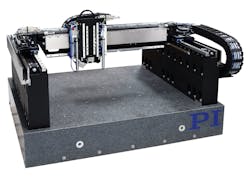
Gantry control In general, gantries have two motors to move the bottom axes, guided by two encoders directing the base of the system. Other control signals also come from side encoders. However, these encoders may generate different readings, and there is the potential for firing in the wrong place. The risk of this happening increases with wider gantry systems with a long cross axis or high dynamics.
Dr. Cliff Jolliffe is head of the automation market segment at Physik Instrumente (PI). Contact him at [email protected].
