How to verify transducer readings are translated correctly
In a control system, a transducer converts a physical phenomenon from the real world into a signal that a controller can process, act on or display. It can be difficult for the person programming or troubleshooting the system to know if this conversion process is being done correctly. Here are some tools to ensure that the readings from the transducer are accurately translated into values that you and your control system can rely on.
Humans live in an analog world. Everything your senses can discern can be captured by a transducer in a continuous signal. This signal, such as the temperature outside, does not exist in discrete steps. We may say it is 19 °C, but of course it is really some infinite fraction between 18 and 20. We round this to a whole number because it is unnecessary to say, “It is 19.0125 °C outside.” Try saying this to a human and see their response.
Machines live in a digital world. In their world everything is in the form of a one or a zero. An analog sensor will convert the real temperature into a voltage, typically, 0-10 Vdc, or current, typically, 4-20 mA. This analog signal is translated through an analog-to-digital converter (ADC), where it is converted to an integer value. The conversion is based on a bit resolution. The higher the resolution, the more precise the integer value will be.
For example, a 12-bit converter ranges from 0 to 4,095. This means there are 4,096 discrete steps that a voltage or current value can resolve to. A 16-bit converter ranges from 0 to 65,535. This means there are 65,536 steps that a voltage or current value can resolve to.
These 65,536 steps must then be scaled to the values that make sense to a human. This is done with the formula of:
((value-min) / (max-min)) * (scale max – scale min) + scale min = value in engineering units
The min values are needed because in a 4-20 mA scale the min is 4 mA, not 0. The 4 mA will correspond with a 0 in the scaled value.
Let us assume that we are working with a 4-20 mA current signal and a 16-bit ADC. The temperature reading of 19.0125 °C will correspond to a current level of 7.042 mA from the transducer. The range of the temperature probe is 0-100 °C, so those will be the min and max scale values. We want to have a decimal point in the reading so a 32-bit floating point number is chosen for the output.
For an ADC with 16-bit resolution, the value of 7.042 mA will land on a step value of 23,074. This can be calculated with the formula:
Max * (current/max current), or 65,535 * (7.042/20) = 23,074
The scaling math will then be:
((23,074-13,106) / (65,535-13,106)) * (100 – 0) + 0 = 19.0125
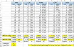
The complete sheet is available for download.
Programmable logic controllers (PLCs) have scaling instructions where the only required values are In Min, In Max, Out Min and Out Max. These instructions automatically do the math.
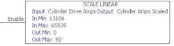
The Scale Linear function scales this value into engineering units, which are whatever units are needed to make sense to a human reading them. These values will normally correspond to the sensor range. In this case the current transducer has a range of 0-50 Amps. The output tag “Cylinder Amps Scaled” will update continuously with a value that can be displayed on an HMI or used conditionally in the program to trigger an alarm or event.
On some older PLCs there are no scaling instructions. For these, you will need to bring in the signals and do the math manually.
Even if the math is done automatically, it is very helpful when troubleshooting systems to understand the calculations being done. If you have a milliAmp process clamp meter you can measure what the incoming 4-20 mA level is and confirm that the system is reporting the correct values. This can be a very valuable tool for troubleshooting analog signals.
Transducer measurements and accurate signal processing can be very critical to a process. Proper scaling is necessary for both humans and machines to react correctly. Using the right tools and understanding the math behind the data will ensure that you can trust the measurement data that is used in your control system.
Larry Stepniak is electrical engineer at Flint Group. Contact him at [email protected].
About the Author

Larry Stepniak
Flint Group
Larry Stepniak is electrical engineer at Flint Group. Contact him at [email protected].
