A Visible Cutting Edge
By Yvon Hubert, Comact Equipment Inc.
There isn’t an industry around that doesn’t have to keep getting better. Manufacturers have enormous competitive pressures to improve yields, quality, throughput, and labor costs. Much of that pressure lands squarely on the shoulders of machine builders serving those manufacturers.
That’s how it is for Comact Equipment, Boisbriand, Quebec, a well-known developer of sawmill technology and equipment for the lumber industry. Our company offers a line of products from basic conveyors to complete, automated production lines.
To help our customers optimize yields in a highly competitive lumber industry, Comact uses machine vision as a key performance sensor. The company has used a camera/laser setup for geometric reading since the ‘80s, and its use of color vision technologies began about five years ago.
Scan and Optimize
In machinery used for the linear transport of tree trunks, machine vision precisely identifies each tree trunk’s shape to optimize cutting operations. “A triangulation method and an optimizer lets us determine how to cut a given trunk to get the maximum amount of usable wood,” says Guy Morissette, development engineer at Comact.
Scanning is a snap
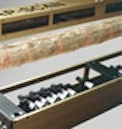
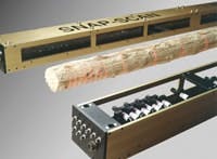
Figure 1: Snap-Scan uses many lasers and cameras to build a complete 3-D shape of a moving or stationary log with a single “exposure,” with a laser line every 4 inches.
Photography courtesy of Comact Equipment
The log first goes through a rotation scanner, which builds a 3-D shape, which is used by the optimizer to find the rotation required for proper orientation. The optimizer sends the rotation solution to the PLC before the log arrives at the log turner. The PLC controls the rolls that rotate the log. During the rotation, another scanner—the correction scanner—examines the log to do any needed rotation correction. If the real rotation of the log is not precisely what it was supposed to be because of knots or butts on the log or hydraulic pressure variation, the optimizer provides feedback to the PLC to rotate the log a bit more or less. Once the log is rotated, it goes through the infeed of the machine. This uses another scanner to align the log in the canter heads. Most OLI machines will have saws to cut side boards after the canter heads. The side boards will fall at the outfeed in a conveyor, and the cant (the log with two plane faces on each side) goes to the next cutting machine.
Electric drives and motors power the saws and canter. Hydraulic-powered servo positioning is used for saws and canter positioning.
Hardware Choices
To perform the optimizer analysis, two to 25 area cameras are used and up to 80 Lasiris laser scanners perform the triangulation calculations.
We were using Pulnix TM-7, TM-200 or TM-250 area cameras, and to efficiently capture the large number of images required, our company chose a Dalsa imaging board with four asynchronous acquisition channels.
"Because we can connect up to four asynchronous cameras to this board, we were able to eliminate the synchronization circuits Comact needed with other boards,” explains Dalsa’s vice president of sales and marketing, Philip Colet. “The high-speed imaging board performs simultaneous acquisition at up to 40 MHz digitization per channel from up to four camera channels.”
Each channel, says Colet, features an A/D converter, synchronization circuitry, anti-aliasing filter, input lookup tables and the ability to respond to four independent trigger events. Buffer image data can be stored in local memory during heavy PCI bus traffic, helping to increase acquisition speed and host availability for processing.
So today instead of using the coaxial camera and a grabber card, we’re using Dalsa’s Ethernet Genie camera.
Dalsa worked with us to develop a new dedicated protocol for this application to compress the digital video signal. This type of camera allows us to scan at speeds of 120 Hz and is being used successfully in almost all of the geometry scanner system replacing coaxial cable technologies. “Ethernet eliminates the need for frame-grabber boards, which lowers the cost, and is more flexible because no specific backplane with PCI slots is needed” says Morissette. Most of the configurations that needed switching with the coaxial camera are now all software programmable.
Comact used JAI, Panasonic and IVP cameras before, but now standardizes on Dalsa for homemade scanners.
“We use Hermary and LMI products, if required by the customer,” says Morissette.
Images are transferred to a PC for processing and optimization analysis. “The image analyzer detects the laser slices on the trunk and builds a 3-D shape. Then the optimizer determines what products can be cut from each shape,” says Morissette.
Our Snap-Scan (Figure 1) uses many lasers and cameras because it builds a complete 3-D shape of a log with a single “exposure.” There is one laser line every 4 inches for a 4-in-scanning density. Scanning is done with the log in motion or stationary.
“By comparison, our C2 builds the complete 3-D shape with only two lasers and cameras,” says Morissette. "The scanning is synchronized to the movement of the log along the conveyor using a shaft encoder. The log must be moving to build the shape. All the scanners are geometric only. They use laser/camera triangulation to build the shape.”
The solution then is transmitted to the PLC. When we choose the controller, we use Allen-Bradley, but our system works with any kind of PLC.
A manual operator doing the optimization versus a machine vision optimization often can mean one less board from every trunk, states Morissette. The precise readings of the machine vision system will cause the cut pieces to have higher values (better grade) because the saw positioning is optimized.
Making the Real-Time Grade
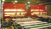
Comact’s customers also reap the rewards of machine vision on our new GradExpert grader, which evaluates the quality of the lumber that results from the optimization and subsequent cutting described. The GradExpert is used at the planner mill to scan dried and planned boards (Figure 2).
Make better grades
Figure 2: With a 3-D scanner and a color machine vision system to detect rot, knots and cracks, GradExpert determines the quality grade of each piece of cut timber.
Photography courtesy of Comact Equipment
“Using machine vision dramatically increases throughput and provides more reliable inspections and more accurate grading than human operators can perform,” says Morissette. “It can scan 220 boards per minutes at 40 in/sec. It would take at least three people to do that.”
High-frequency fluorescent tubes light each piece of wood. Two to 10 Basler L301BC line scan cameras and image capture boards from Dalsa acquire images at speeds to 160 Mbps in search of defects that would affect the grade of each piece. This optimizer program sends the solution for each board to a PLC, which controls the sorting.
“The image-capture board from Dalsa is a single-slot video acquisition and preprocessing board for the PCI bus that features high-speed, high-quality image acquisition and handles a variety of data formats including eight, 16, 24 or 32 bits/pixel,” says Colet. “Hardware speed is crucial to the success of the application, which demands real-time acquisition and processing of images.”
A PC-based architecture helps us achieve our performance goals, says Morissette. “In addition, programming is simpler and we chose to do all the programming on the PC instead of using DSP boards,” he says. “It’s easier to program and easier to stay up to date with new technologies. The frame grabber has a driver to Basler’s L301BC line scan camera, so we saved the time and money involved in developing a driver from scratch.”
Another reason Comact chose Dalsa image-acquisition boards is the ability to integrate with the QNX real-time operating system via simple serial interface, says Morissette. “We develop all our software in-house, from drivers to the user interface, using QNX technology.”
Rolling and Supporting Our Own
We write our own application code because it gives us more flexibility and produces better solutions for our customers. We can adapt to problems more rapidly with our own engineers. “It is very rare that we can use a vision company’s algorithm directly to detect a wood defect,” says Morissette. “We deal with many wood species with many variations in textures and defects, since we sell systems in Canada, U.S., Chile, Brazil, Australia, and other locations around the world.”
Likewise, the company doesn’t plan on using self-contained “smart” cameras. “Smart cameras are good for well-known applications like detecting defects on metal or paper sheet, or to recognize objects that are always the same,” says Morissette. “It doesn’t do well with wood defects.”
Morissette says this doesn’t pose problems in training customers to use their software. “We have a department of process wood specialists who do the training and write the training documents,” he says. “They come from the industry, so they speak the same language as the customers. Training and user-friendly software is very important.”
Yvon Hubert is vice president of Comact’s Optimization and Control division. You can contact him at [email protected].


