How to design a machine vision system

Key highlights
- A machine vision design process template consists of 12 steps. The inclusion of additional steps is often necessary due to a project’s unique requirements.
- Most commonly, lighting is the biggest challenge. There are resources to help with designing lighting and expertise available to assist with a good design.
- Continuous testing and refinement of the design helps to avoid the potential cost of a change discovered late in the design. The refinement of the design makes clear there are loops in the design process steps. Just how many and where the loops are, is dependent on the project’s complexity, the attention to design detail and the quality of testing.

Vision System Design
PERRY WEST
AUTOMATED VISION SYSTEMS
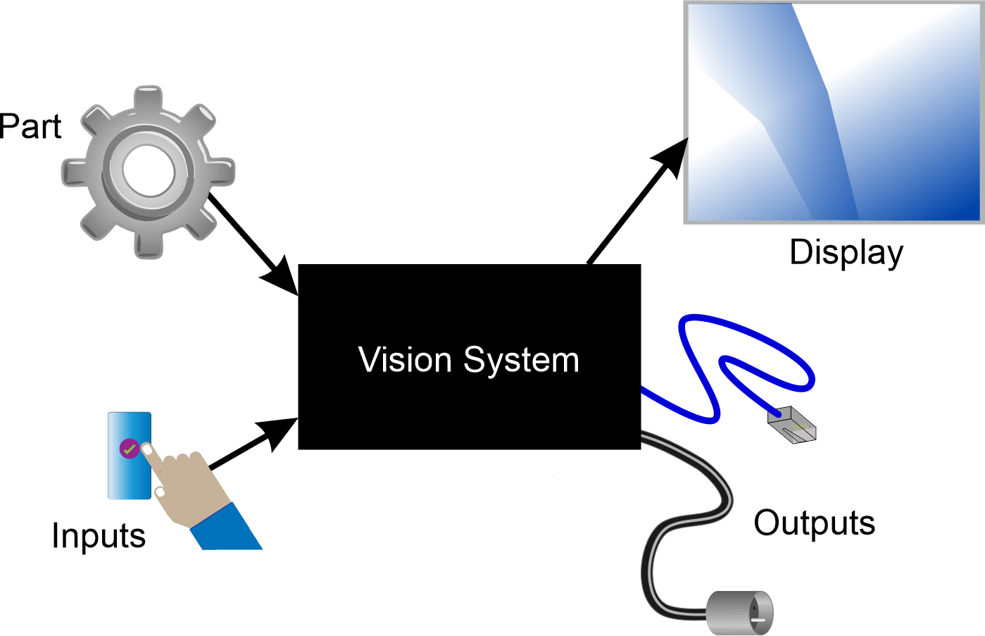
When you start the design of a vision system, it’s simply a black box. You need to know the inputs and outputs to begin to resolve the black box into its component parts as a vision system (Figure 1).
Inputs are the parts the vision system will view, connections to other equipment and the operator controls. Outputs are displays to the operator and the signals to connected equipment. You need a design to bring them all together.
A requirements document needs to specify the inputs and outputs along with other information such as speed, environmental requirements and other constraints.
Ideally, there is also an acceptance test procedure specifying how the vision system design will be evaluated to ensure it meets requirements. The vision system specification emerges from the design process. It includes specifying components, such as camera, lens, light, processor and software, as well as how to position them. This information typically comes from tests and experiments. There is almost always additional information needed on interconnected equipment.
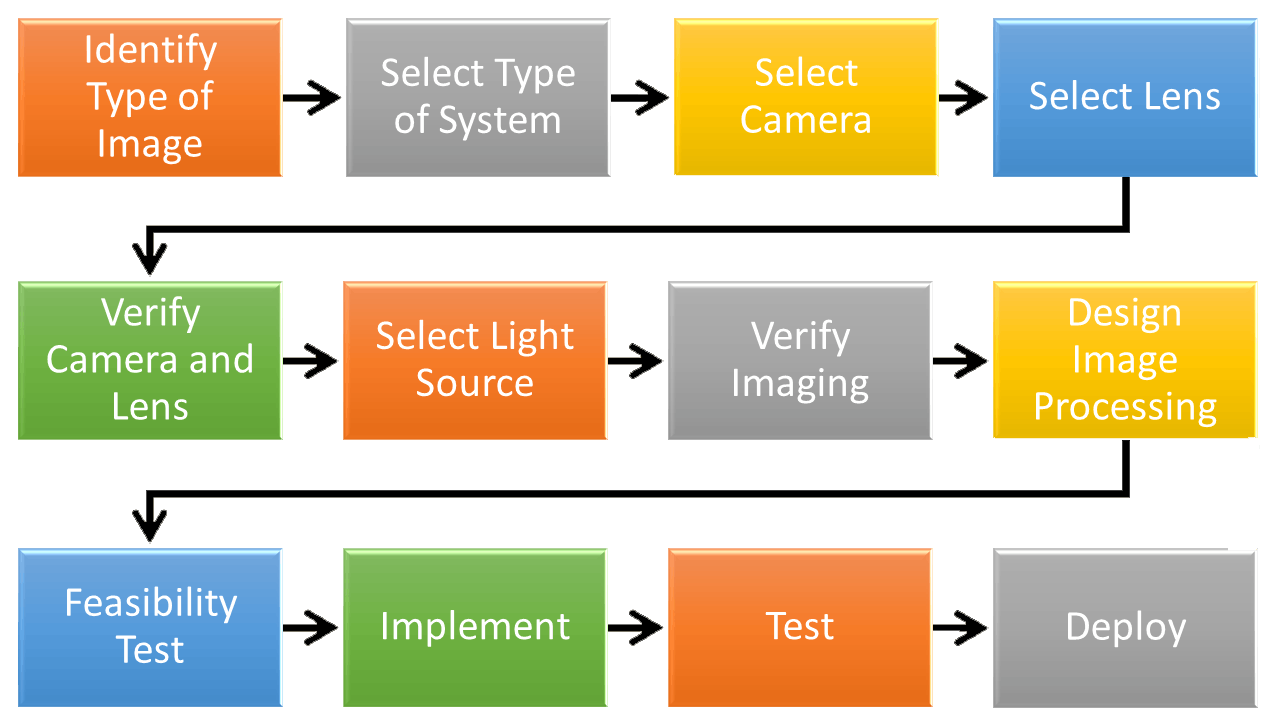
Figure 2 shows the process as being linear. This is a “typical” process. The requirements of the application sometimes dictate working in a different order. However, when designing a black box, such as a vision system, it is always necessary to start with what is known or specified, in this case the inputs and outputs, and progress toward the middle. A common mistake is to start with image processing, which is in the middle of the process, without knowledge of the characteristics of the image, which is determined by the earlier steps.
Always plan on the process having loops back to previous steps as the design progresses. At each step, it is possible that some previous component selections will turn out to be unacceptable. For example, after selecting a camera, it may turn out there is no acceptable lens for the particular camera, and a different camera needs to be identified that will have a compatible lens.
Type of image
Start the vision system design and its specification by identifying the type of image. There are a number of different images used in machine vision. Among the common choices are:
- monochrome—the gray-scale image is the most common in machine vision
- color—usually consisting of three bands in the visible light spectrum: red, green and blue
- multi-spectral—comprising several discrete spectral bands that may extend into the infrared
- hyperspectral—comprising a large number of adjacent spectral bands that may include both the visible and infrared spectrum
- 3D—where the image contains height or distance information
- X-ray—where the image shows internal details of the imaged objects.
Identifying the type of image also entails estimating the number of cameras needed. When the vision system needs multiple views of the scene, multiple cameras may be needed.
Type of vision system
Once the type of image and number of cameras are known, the type of vision system can be identified. Seven basic choices are available.
- Component: Each component of the vision system— camera, lens, light source, image processor and software is individually specified and selected. Commonly a component vision system uses a PC as the processor and sometimes includes auxiliary processing boards, if necessary. The component vision system easily accommodates multiple cameras when needed.
- Smart camera: This comprises a single unit containing the camera, image processor and software. Some smart cameras come with lenses and lighting that may or may not be appropriate for the application. However, the selection of a smart camera when multiple cameras are needed may or may not be economically attractive.
- Embedded: Typically this is a board level camera with attached processor that is designed for lower-cost, higher-volume designs. Generally, an embedded vision solution is a single camera solution. It does not typically include a lens, a light or the necessary image processing software.
- Modular: This is a suite of compatible components, including camera, lens, light, processor, software and interfaces from a single manufacturer. These typically accommodate more than one camera when needed.
- Application-specific: A vision system can be configured for a specific application. If there is an application-specific vision system available that addresses the application, it is usually the most economical because it eliminates the engineering overhead to perform the vision system design effort.
- Robot vision: Many industrial robots have vision systems available already integrated into the robot controller. If the existing robot’s vision system can meet the vision system requirements, it saves a considerable amount of development time over using a different vision system and developing the interface with the robot.
- Custom: Fully custom vision systems are extremely infrequently required. The range of existing cameras, lenses, light sources, computers and software packages can meet almost any application. Only in rare instances is it necessary to design a custom camera, have a custom lens designed, develop a truly unique light source, use some unique computer components and/or write the image processing software from scratch. Only projects that need to be scaled to very high quantities can justify the much higher engineering cost of a custom vision system.
Camera selection
Make an initial camera selection. The type of image and therefore generally the type of camera is already identified. Camera selection is dictated by the needed image resolution and the camera interface to meet speed and cable length requirements.
Image resolution for area cameras is the number of rows and columns of pixels needed to meet the vision system’s requirements. Some vision-system developers tend to shortcut this step and pick a very high-resolution camera that far exceeds what is needed. That approach has several drawbacks.
One drawback is a decrease in speed due to more image data to transmit and process. The loss in speed can be mitigated by using more image processing power. Still, the camera will be more expensive than one that has only the image resolution needed. Also, the lens to cover the larger image sensor or to meet the resolution needed for smaller pixels will also be more expensive.
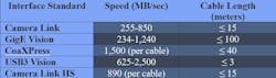
For industrial vision systems, there are a number of camera interfaces available depending on speed and cable length required. Table 1 shows the common camera interface standards. In addition to speed and cable length, there are many other attributes that should be investigated including power delivery and data reliability.
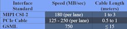
For embedded vision systems there is no specific suite of interface standards. Three standards seem to have the most use. These are summarized in Table 2.
Lens selection
The first step in selecting a lens is to determine what type of lens is needed. Most applications are readily solvable with normal fixed focal length lenses, often called factory automation (FA) lenses. Some applications need to be insensitive to working distance variation and may benefit from a telecentric lens. There are also several different specialized lenses for such things as imaging the inside of a hole or the outside of a cylinder from the top.
Lens selection for a factory automation lens is guided by:
- size of the image sensor
- size of pixels on the image sensor
- working distance
- size of the field of view
- camera’s lens mount
- need for ruggedization.
There are two approaches to selecting a lens. One approach is to perform a series of basic calculations, typically using a spreadsheet for easy exploration of options. The few equations needed are readily available from a variety of online resources. The second approach is to use one of many online lens selection calculators. The advantage of performing your own calculations is flexibility in choosing a lens. The advantage of the online lens calculator is ease of use, and it often also has more accuracy in results than possible using just basic formulas. The disadvantage of the online calculators is their limited scope of alternatives; they’re usually limited to products the company providing the calculator offers.
Test the camera and lens
This test step should also include evaluating the depth of field and relative illumination of the lens. The depth of field is a function of the aperture, or f-stop, of the lens.
The f-stop also affects the lens’ resolution and light-gathering power. Because the f-stop affects all three parameters, it is good practice to set the f-stop to give only the needed resolution and depth of field. Light-gathering ability of the lens is better compensated for by adjusting the exposure time or the illumination intensity from the light source identified later.
Relative illumination is the fall-off of light-gathering ability of the lens across the field of view. Normally, the light-gathering ability is the highest in the center of the image and falls off as the distance away from the center increases.
Design the lighting
Designing the lighting means identifying the lighting technique, as well as identifying the specific make and model of light source to provide that lighting.
Because most people working in machine vision have a limited background in optical physics, this step can be the most challenging. Lighting is the primary determinate of contrast in the image, and contrast is the signal for image processing. Good lighting makes the vision system easier to engineer and more reliable in operation.
There are many resources available on designing lighting for machine vision. If optical physics is not one of your strengths, do some studying before designing the lighting; or you can engage someone who has the needed skill in lighting design. Remember the cardinal objective, not the only one, is to create contrast. You must consider not only the feature you want to image, but also its background to create the contrast.
Sometimes the initial lighting method produces less contrast or less reliable contrast than desired. Having at least one alternate approach can be very beneficial to the project.
Test the camera, lens and light
Using actual sample parts and the specific camera, lens and light source of the design, ensure the contrast is reliable over the range of parts, part locations and part rotations. Also, check that no unwanted artifacts, such a glints, glare or shadows appear in the images. This test step is also a good time to gather sample images to help develop the image processing.
Carefully document the setup, including accurate dimensions. There are times when the implemented setup does not give the same quality of results as the test setup due to what seems like a minor difference.
Get your subscription to Control Design’s daily newsletter.
Design the image processing
Designing the image processing often takes testing and refinement. This process proceeds more efficiently if there is a suite of stored images for testing and development, rather than needing to repetitively load and unload parts.
The first part of designing the image processing is picking the software package. As mentioned, writing custom software from scratch is only justified when no existing software package can perform the task. Most of the popular machine vision software packages offer both conventional image processing algorithms, often called rule-based programming, as well as artificial intelligence (AI) capability.
Although AI is commanding a lot of attention as a means of processing images for machine vision, the classic rule-based programming may actually take less effort for many machine vision applications than using AI. For example, making measurements of a part is unsuited to AI as it exists today. Finding a part’s location is more accurate and reliable with existing rule-based algorithms than AI’s ability to provide location. On the other hand, finding and classifying defects is much easier with AI than crafting many rules by hand through trial and error.
Both AI and rule-based approaches may benefit from some preprocessing of the image. Well-designed lighting that gives high contrast where needed and suppresses unwanted features can often eliminate the need for preprocessing.
Rule-based programming, by nature, requires final interpretation: which part is present, or is the part good or bad? Even AI may need final rule-based interpretation. For example, if a network is trained to recognize cats and dogs, it is possible for some image it will say there is a 50% possibility of a cat and 50% probability of a dog. What action the vision system should initiate requires creating some rules to handle these types of situations.
Feasibility test
There is a final feasibility test to ensure the imaging and image processing work reliably together. This test must use the actual vision system components in their designed positions, as well as actual parts placed under the camera. Do not use stored images for the feasibility test. The test should include checks on accuracy and reliability of the results, as well as verification of speed. Document this test carefully. Plan for refinement of the vision system design during the feasibility test as this is quite common.
Implementation
Implementation involves building and installing the vision equipment into the actual environment along with developing and debugging the interfaces to external equipment. It is common for interface implementation and testing to take a significant amount of the vision system engineering effort.
Incremental testing, somewhat similar to the feasibility test or the testing described in the next step, is desirable during implementation to avoid needing to make major modifications and repeat all the tests.
Testing
Testing after implementation needs to be extensive. This testing confirms not only that the vision system is working but the inputs and outputs, both with the operator and with connected equipment, work correctly. It is much easier to fix any issues uncovered during testing and before deployment. For example, if a problem is detected during testing, it often can be fixed and testing resumed. If the problem is uncovered during acceptance testing, then the whole acceptance test needs to be rerun to verify no new problem was introduced.
Deployment
Deployment involves running the factory acceptance test (FAT) before shipping, installing the vision system into the production environment and rerunning the site acceptance test (SAT) on site.
The FAT and SAT are similar. However, some elements of the FAT, such as checking the workmanship and verifying required operator functions are present, does not need duplication during the SAT. Likewise, there may be elements that cannot be adequately tested during FAT, such as the interface to unique production equipment, that are essential parts of the SAT.
Deployment also includes providing necessary operator and maintenance training.
Additional tips
Here are a couple of ideas that can make vision system design progress much more smoothly.
- Write a sparse draft of the operation and maintenance manuals as part of developing the vision system specification. The draft will identify most needed procedures, which will be detailed as the vision system development proceeds. Keep the manuals updated as the design progresses. By the time the vision system is ready for FAT, the manuals should be very close to complete.
- Don’t forget about calibration of the vision system. Identify the calibration needs and tentative procedures early so a calibration target can be purchased and used for testing. Also, any mechanical design can take into account how the target is fixtured for calibration.
Next steps
- For a potential vision system application, begin drafting a requirements document outlining the necessary inputs (parts, connections, controls) and desired outputs (displays, signals to equipment).
- Based on the application requirements, start to identify the necessary type of image (monochrome, color) and estimate the number of cameras that might be needed.
- Review the seven basic types of vision systems to determine which approach might be the most suitable for the intended application and integration with existing machinery.
About the Author

Perry West
Automated Vision Systems
Perry West has led Automated Vision Systems as president for more than 45 years. Contact him at [email protected].
Other articles by Perry West include:

Leaders relevant to this article: