Light-fidelity communication: technology in progress
Light-fidelity (Li-Fi) wireless communication systems have seen many improvements in recent years. The Li-Fi instrument network can actually enhance communication systems, and the detail design specification is reference material that may not prove to be 100% implementation-ready but will help those who try to explore and advance this area as a technology in progress. First, the two major and modules of the system are the optical wireless instrument (OWI) and the optical access point (OAP).
Optical wireless transmitters are constituted by a sensor for real-time measurement of process-variable information and the timely transmission per update rate of the OWI to the OAP via the optical signal.
Optical wireless control elements are constituted by the control element and the light-sensitive module, which receive the optical signal at the light-sensitive sensor and convert it into a respective electrical signal to control the process variable.
The optical access point (OAP)/transceiver modules comprise light-emitting diode (LED) lights, light-sensitive sensors such as photo-detector or solar-panel, high-speed LED drivers, amplification and processing modules and power modules. The light-sensitive sensor is connected to an optical receiver or signal processing and amplification module, which processes the process-variable information transmitted from the optical wireless transmitters and sends to the programmable logic controller (PLC) or distributed control system (DCS) in the local control room (LCR), local electrical room (LER) or substation (SUB) via redundant fiberoptic cable. The switch control module converts the control signal from the PLC/DCS into a switching signal of a specific frequency. The high-speed LED driver receives the switch signal, which is converted to LED flashing lights-optical signal. Intrinsically safe battery packs or renewable energy such as thermal, solar or vibration/wind power the light-sensitivity sensor module, LED array and processing module.
Detailed design specification
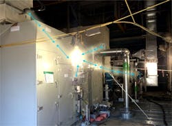
The effective range of an optical wireless instrument is based on the linear distance between the OWI and OAP, when in the presence of the process infrastructure inside the module. Typically, if the OWI and OAP have no obstacle between them and have direct line of sight (LOS), and if OWIs are mounted in the effective lumens area of OAP, then the data transfer between OWI and OAP will be very high (Figure 1).
Figure 1: If the OWI and OAP have no obstacle between them and have direct line of sight (LOS), and if OWIs are mounted in the effective lumens area of OAP, then the data transfer between OWI and OAP will be very high.
The effective range of an OWI and OAP also depends on the illuminance of the LED lights. If the OAP and OWI are constituted of low-illuminance LED lights, then the effective range between them will be less—minimum 3m in direct line of sight. Similarly, if the OAP and OWI are constituted by medium- and/or high-illuminance and guided red/green/blue (RGB) LED lights, then the effective range will be high.
Obstacles decrease the effective data transfer rate, if it is not a clear line of sight. The main problem with the Li-Fi wireless instrument communication network is the optical signal can’t go through the objects or doesn’t penetrate through solid objects. If either the OWI or the OAP is blocked totally in anyway, due to design or workmanship ignorance, then the optical signal will instantly cut out or cut off.
Most process environments have a high density of equipment, pipelines and structural metals that reflect optical signals in a nonpredictable manner and reflect the optical light signal off of the metal of the surrounding environment. This high density of metals in the environment will not affect the range of OWI and OAP, because direct line of sight is not necessary for OWI and OAP to transmit a signal. Light reflected off of walls, objects, structures, pipes or equipment can achieve a 70 Megabits/second (Mbps) data-transfer speed.
The effective range of OWI and OAP in the environment inside modular projects can be split into three categories.
- Highly dense environment (3–5 m or 10–15 ft). This is the typical, highly dense plant environment inside the modular structure where equipment, number of instruments, pipelines and structure metal are very dense. In this type of environment, objects or metals are present in the environment and are reflected off of the optical signal, which affects the data transfer speed (70 Mbps), but not the range of OWI/OAP.
- Medium dense environment (8–10 m or 25–30 ft). This is the medium dense process area, where the appropriate space exists between the equipment and structure. In this type of environment, the data transfer rate shall be slightly less than its average high rate.
- Light dense environment (10–12 m or 30–40 ft). This is the light dense environment, where the optical signal gets clear and direct line of sight between OWI and OAP. The data transfer rate shall be average high rate.
These values for effective range of OWI and OAP are theoretical guidelines and are subject to change with practical modular and site tests in different types of environments. Three factors significantly minimize or obstruct the optical signal.
- Mounting the optical wireless field instruments above the OAP can cause the optical signal to not be received by optical access point.
- Mounting the OWIs outside the closed module may interfere with or obstruct the optical signal.
- Mounting the optical wireless instrument isolated from the network by an enclosure/heat box/insulated blanket blocks the optical signal to transmit and/or to receive. A small fiberglass device enclosure is an appropriate solution for such a harsh application or environment, due to its clear, transparent nature.
Li-Fi OAP network design
The installation of the OAP affects the OWI performance, which ultimately reduces the system performance. The closed module of any process area shall include multiple OAPs. Therefore, the optical signal from an adjacent or nearby OAP causes interference, which limits the signal-to-interference-plus-noise ratio (SINR). It isn’t possible for the OAP/OWI to transmit a coherent optical signal due to the use of LED lights and the requirement that the information has to be encoded by changing the amplitude of the light (turning on/off). To avoid interference of the optical signal from a neighboring OAP and to provide multi-instrument access from the same OAP, the popular frequency reuse concept can be applied. As per the frequency reuse concept, the available frequency can be divided and shared among the different OAPs (www.controldesign.com/whatislifi, www.controldesign.com/advancedmobile).
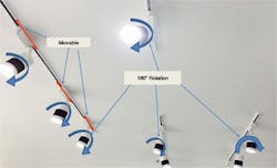
The network models evolved for radio frequency networks shall be applied for Li-Fi, due to the uniform signal coverage. Similarly, the lighting is designed to brighten the whole area in a consistent way (www.controldesign.com/en12464-1). Different OAP network models can be evaluated and considered (Figure 2).
Figure 2: The lighting is designed to brighten the whole area in a consistent way.
The hexagon network model is a conventional hexagon topology that is well-known and widely used in radio frequency cellular applications. This is a standard model, in which OAPs are located or installed in a sequential manner to form a grid of identical and Voronoi-diagram hexagon shapes to form a network.
The square network model is a square lattice network model, in which OAPs are located or installed in a way to form a grid of identical and square-shaped Voronoi-diagram cells.
The square network models are better-suited in a large area to brighten up the entire space, as compared to a hexagon network model. However, the inside modular environment typically contains a number of unpremeditated objects such as structural beams, electrical lightning, equipment and pipes. Therefore, it will be difficult to examine the performance of such a network in reality.
The spatial point processes are useful as a statistical model in the analysis of observed patterns of OAP and also provide more accurate solutions for the network interference model.
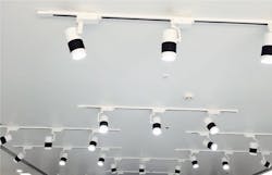
The Poisson point process (PPP) network model is the most common and widely used spatial point process model (www.controldesign.com/cellularnetworks). The number of OAPs is considered to follow the Poisson distribution, and the OAPs are geographically independent to each other. This model is unrealistic, due to its unpredictability in nature. Sometimes two OAPs can be arbitrarily close to each other. It may represent scattered objects such as transmitters in a wireless network (Figure 3).
Figure 3: In the Poisson point process network model, OAPs are geographically independent to each other. This model is unrealistic, due to its unpredictability in nature. Sometimes two OAPs can be arbitrarily close to each other. It may represent scattered objects such as transmitters in a wireless network.
The hard core point process (HCPP) is similarly a spatial point process, which includes additional parameters that control the minimum separation between any two OAPs in order to limit the negative effects of the PPP model.
Based on practical observation and comparison of the SINR for each of the four different network models in cumulative density formation (CDF), the hexagon network model yielded the best performance, followed by the square network model and then the HPCC network model. The worst performance came from the PPP network model (www.controldesign.com/whatislifi).
Spare capacity, redundancy and signal propagation
During a typical project, there’s often a requirement to provide installed spare hardware, such as marshalling cabinet, I/O cards, space in cable tray and terminations, as well as additional spare space. These values could vary between 20% and 30 % depending upon the specific project. The consideration when designing with optical wireless instruments on a Li-Fi instrument communication network is no cabinetry marshalling, I/O cards or termination is required. It will only add OAPs in the communication network as per the Voronoi-diagram network model to increase the OWI’s capacity if required in future.
The Li-Fi instrument field communication network is inherently redundant between the OWIs and the OAP. Consider these provisions to maximize system performance and improve the communications network.
- Provide accurate and safe grounding to the OAP and OWIs, as per standard electrical code, to avoid unnecessary voltage fluctuation. Improper grounding causes network failure.
- Provide proper surge protection to the OWI and OAP for instruments installed outside of the module.
- Always use redundant power and an uninterrupted power supply (UPS) for OAP. This is the main source of OAP failure.
- If measurements are critical, make sure the illuminance for the modular-field-network OWI is direct line of sight.
- Make the OAP connection to the industrial-control-system (ICS) communication cabinet redundant. This includes physical communication Ethernet/fiberoptic switches, power supplies and fiberoptic cables up to the DCS.
The Li-Fi instrument communication network also faces different types of difficulties in transferring data or media via optical signal, which may also impact the quality of data received by the OWI/OAP, such as interference by another light beam, intersymbolic interference, nonlinear signal distortion, low illuminance and co-channel interference (Figure 4).
Figure 4: The Li-Fi instrument communication network also faces different types of difficulties in transferring data or media via optical signal.
These problems in Li-Fi instrument communication network are detectable and easily removable. It’s very secure because light doesn’t penetrate through walls.
ALSO READ: 12 steps to Li-Fi implementation

Leaders relevant to this article:


