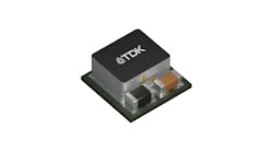
While the switching power supply data sheet may document compliance to over two dozen general specifications, focusing on the input and output specifications and the safety standards that impact installation highlights some of the basics of specifying and integrating the device.
Most power supplies have the input voltage well supported with a nominal range of 85-264 Vac suitable for use with any 115- to 230-Vac supply. The typical voltage frequency range covers any 50- or 60-Hz supplies, as well.
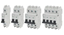
From an integration standpoint, things start getting interesting when discussing nominal current and inrush current. It is common for the input to most power supplies to be internally fused, but adding supplementary fusing or, preferably, a miniature circuit breaker (MCB) to the input that can be turned off and on is best practice. The full load input current is noted in the data sheet and fusing between 150% to 500% of the specification, and wiring with suitable gauge wire, is appropriate. For example, when wiring 2 A to 10 A switching dc power supply, include a 10 slow-blow fuse or MCB and 16 AWG wire to protect input wiring.
However, be certain that the fuse or MCB can handle the inrush current. While the inrush duration is less than half an ac cycle, it can be six to 20 times the full load input current. This can certainly trip fast-blow current protection devices, so check the manufacturer’s recommendations as slow-blow fuses and circuit breakers are likely needed.
The power supply output voltage and the nominal output current or maximum output power are likely the most important specification for the application, but there is more. From the voltage side, there is output adjustable range, overvoltage protection, voltage tolerance and ripple to consider. These output-voltage specifications can impact sensitive applications, such as analog circuits or test systems, but most 24 Vdc power supplies can deliver the needed potential.
The output current may need a closer look—specifically, nominal output current and current limit method. This includes protection against short circuit and overload. This power-supply output protection often resides internally to the device, but that doesn't mean additional protection is not needed when integrating it.
Short-circuit protection is often built-in to the power supply and will shut off output power when a short circuit fault occurs. The input power typically will need to be cycle off to on to reset this fault.
Many power supplies use a feed-forward current limit method on the output. This limits the maximum overload current to 110%, 150% or 200% of nominal current, depending on the power supply selected. With this method and when an overload condition occurs, the current continues to rise to the limit, but the voltage drops to maintain constant power. This disrupts the constant voltage feature of a power supply but can help to start an electric motor with high inrush or power through other high-inrush events.
These feed-forward current limit events may cause devices, such as cameras, light curtain controllers or safety relays, to intermittently lose power. The switching power supplies' built-in protection from overload can also affect the output protection methods required. Adding fuses, MCBs or electronic-circuit-protection (ECP) devices to the output circuit can help to capture and isolate the circuit causing the overcurrent by tripping the protection device.
Translated to design considerations, that means to separate high-inrush dc circuits, such as motors, from low-level circuits, such as controllers, HMIs and safety relays. Distribute the dc power output through multiple protection devices such as fast-blow, non-time-delay or slow-blow circuit breakers depending on the connected load. For even better detection of overcurrent faults, the ECP monitors both current and voltage. A prolonged undervoltage condition can help to indicate the circuit causing the problem.
Designing the dc power distribution to feed power through multiple protection devices also enables the use of smaller gauge wire. The use of smaller wire is common in discrete and analog I/O and other signal cable runs.
The discussion above regarding output short circuit and overload is related to general safety specification, met by many power supplies, for Protection Class 1 (IEC 536 or NFPA 70, Article 725). While Article 725 does cover some low-voltage industrial control, some computer networks and other remote-control, signaling and power-limited circuits, it's as much about usage and power limitations that differentiate it from power circuits.
Class 1 discusses the portion of wiring in the power-supply circuit between the overcurrent device and the connected equipment. Class 1 circuits have a voltage requirement of less than 30 V and a power restriction of less than 168% of the device's Volt-Amp rating, and overcurrent protection is required.
Some power supplies meet Class 2 requirements—upgraded output protection for the connected loads. This class focuses on the circuit between the Class 2 power supply and the connected equipment. It protects the circuit from fire and the personnel from electrical shock.
There are many requirements for Class 2 circuits, but wiring to the power-supply load side does not require a fuse if the proper wire is used. An example of this is power over Ethernet (PoE) cables. Without proper current limiting and wire size, 100 cables together in a bundle could cause quite a fire.


