How to apply industrial control to small-batch distillation: a case study in smart reflux automation
Key highlights
- Apply precise PID control to manage temperature-critical reflux distillation using a peristaltic pump and PLC-based automation.
- HMIs and PLCs, paired with temperature sensors and motion control, can simplify control, monitoring and data logging in small-scale batch processes.
- Integrate Node-Red with PLCs to create a scalable, web-connected dashboard for real-time distillation process insights and remote accessibility.
Creating distilled spirits for beverage use is often more art than science. Concentrating alcohol content without losing distinctive flavors from the fermented mash calls for careful measurement and control of distillation principles to get a desired result. Traditional “moonshine” production conjures images of a pot still, but these are too inefficient for industrial applications.
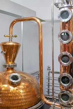
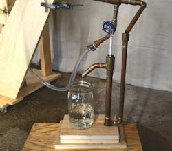
A far better approach—following industrial principles—uses a distillation column with trays or packing, where some condensation produces reflux (Figure 1). Reflux is a technique where the mixture is heated to produce vapor, some of which is then condensed back into liquid, falling back into the column where it is reheated and re-vaporized at a higher concentration.
Consequently, a distillation column allows a higher degree of controllable separation, hence their universal industrial use.
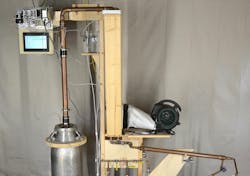
Hobbyist-scale stills are less complex than industrial installations, but it is possible to apply the same reflux concepts. Our small team wanted to try applying big-industry techniques to operate a small-scale pilot still for beverage ethanol production, using a cost-effective yet capable programable logic controller (PLC), human-machine interface (HMI), motor control devices, instrumentation and other automation elements.
Batch distillation basics
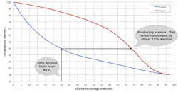
Separation of alcohol and water using distillation is practical because they have different boiling points. Indeed, the boiling point of a mixture depends upon the relative proportions of the two (Figure 2). What’s more, vapor boiled off has a higher alcohol content than the liquid in the boiler producing it, concentrating alcohol as a result.
Creating pure alcohol via distillation works to a high limit of approximately 96%. For beverage purposes, this isn’t necessarily desirable, unless producing vodka, as much of the mash’s flavor profile is lost. Fortunately, the concentration can be easily regulated by controlling vapor temperature.
Creating beverage-grade alcohol usually involves two distillation steps. First, fermented mash with about 10% alcohol content goes through a “stripping run” using a pot still, to raise proof to between 30% and 40%. This is distilled a second time in a “spirit run,” often using a distillation column, to raise proof to a level more suitable for aging and bottling.
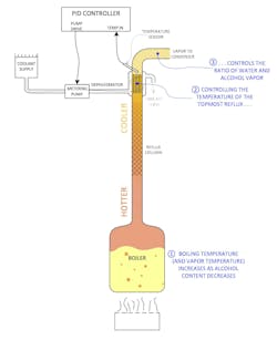
As a quick review of distillation column operation, vapor driven up the column from the boiler interacts with reflux liquid coming down from cooler areas at the top (Figure 3). This allows for higher-efficiency separation via repeated condensation and re-vaporization. The ultimate objective is controlling the vapor temperature, which in turn indicates the alcohol concentration, by varying the amount of cooling.
Adding a dephlegmator—a small shell-and-tube heat exchanger—at the column top provides final vapor temperature control. Condensation from the dephlegmator falls back into the column as reflux. Vapor temperature, measured just above the dephlegmator, is controlled by metering the flow of cool water through the dephlegmator.
In this type of batch operation, alcohol concentration in the boiler is highest at the start, therefore the boiling temperature is lowest. As alcohol cooks off, boiler temperature increases, and the proportion of alcohol to water leaving the boiler drops. Therefore, the amount of cooling necessary to maintain the same vapor temperature at the column top constantly increases, creating more reflux and reducing the ultimate output. Matching cooling flow to alcohol reduction is the essential challenge. Eventually as boiler alcohol nears zero, cooling water flow is highest, either choking off vapor flow entirely, or saturating the pump, making it impossible to maintain the setpoint.
Control strategies
Since cooling water flow control is relatively low—around 8 ml/min—and variable, approaches such as needle valves prove ineffective. A peristaltic pump is a more practical approach, but manual control requires constant attention to compensate for temperature changes.
Our first automation attempt used an Arduino-based controller, programmed to drive the pump. This handled automatic control partially but still demanded manual tweaking and did not provide data integration.
A better integrated system using modern automation hardware offers critical advantages:
- PLCs interface directly with temperature and other sensors, while providing proportional-integral-derivative (PID) control with automatic tuning.
- HMIs provide clear visualization to consolidate setup, control and monitoring, with data logging.
- Stepper motor control via the Click TTL module provides precise peristaltic pump operation.
- Devices can be integrated via Ethernet.
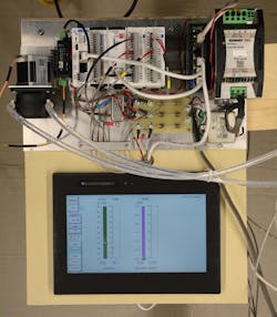
We chose AutomationDirect’s Click Plus stackable micro modular family of PLCs and I/O (Figure 4). It offers considerable processing speed, interfaces to a wide range of I/O signals, including resistive temperature detector (RTD) sensors and high-speed pulse digital outputs for stepper motor control. This PLC integrates easily with the AutomationDirect C-more CM5 touch-panel HMI. By selecting a two-slot controller model, we were able to add a Node-Red controller in the second slot to enhance data connectivity. Two four-channel RTD modules allow connection to temperature sensors:
- boiler
- column top
- final condenser
- dephlegmator cooling inlet and exit.
Top shelf program development
The PLC logic and HMI graphics needed to control and manage the system were developed in parallel for this project. While accurate PID-based pump control would be essential, this would be a data-driven project. All temperatures and the pump output would be logged. Additional calculations and logic would determine the amount of cooling in the dephlegmator, and a recording of which jar of product is produced throughout the run.
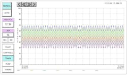
Using the free Click and C-more programming software packages, it was straightforward to connect the RTDs into the PLC and map scaled values to the HMI. The first screen presents and trends these temperatures, using a standard chart object and a 15-second sampling interval (Figure 5).
Pump control was the next task. The SureStep 4830 dc micro-stepping drive operates the pump motor. Conveniently, the Click Plus PLC includes a native motion control block with configurable maximum pulse rate, maximum acceleration and other parameters. An associated HMI screen was developed with a slider for setting motor speed, plus an indicator for motor speed, making it simple to calibrate the pump.
Get your subscription to Control Design’s daily newsletter.
Although the PLC and HMI are closely integrated, functions are divided. The PLC handles all mathematics, logic and control processes, while the HMI provides user visibility and access to controls and information produced in the PLC. Together, they provide all controls and display all process information in engineering units. Advanced features and variables provided by the PLC improved HMI design.
Several HMI screens were produced:
- startup, to set date and time
- controls, providing operational inputs, such as the setpoint and manual pump speed
- temperatures, displaying and tracking various values in the system
- pump, displaying speed and cooling water flow to the dephlegmator
- tuning for the PID loop parameters.
Because PID pump control based on temperature input is a core function, a temperature setpoint slider resides on the Controls screen. Several HMI objects are accessible on all screens, such as buttons to allow easy screen navigation, and buttons for selecting manual or PID pump control.
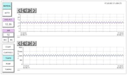
While the I/O signals provide important data, even more information can be derived. Because the peristaltic pump is positive-displacement, its speed indicates coolant flow. Combining this with the specific heat of water allows the cooling rate in Watts to be calculated, with both displayed on the Pump page (Figure 6).
In addition to logging I/O signals and calculated values, the configuration allows users to manually enter externally generated information, such as alcohol concentration measurement and jar number, on the left side of the screen, providing a comprehensive process log. All data is logged to a microSD card slot in the PLC. Configuration is simply performed by adding variables to a list with a specified output format. A comma separated variable (CSV) file allows importing data into spreadsheets for analysis.
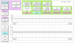
The PLC includes native PID auto-tuning functionality, accessed via the Tuning page, which displays this and allows setting the PID parameters while displaying the process variable and control output (Figure 7).
An additional goal of this project was to make the produced data readily accessible by external systems. For this we used the Node-Red module. Node-Red is a powerful programming tool, based on the notion of passing messages from one processing node to another. Programs are graphical, with nodes selected from a menu, placed in a working area and connected together, linking one node’s output to another node’s input. Many libraries of nodes have been created for accessing data from over the web, formatting displays, processing audio and posting internet of things (IoT) data.
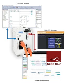
Nominally, Node-Red runs on a web page, and once a program flow is created, it produces code for use on a target system. For the AutomationDirect implementation, Node-Red flows can both read and write variables in the PLC (Figure 8). For our trial purpose we created a simple dashboard webpage displaying key operating temperatures and parameters and kept this local to our own isolated and private network. However, Node-Red provides an easy and secure way to extend data connectivity throughout a much larger operation, and even over the internet. In our case the goal was to produce data, but Node-Red also makes it easy to consume externally sourced data, such as a weather report or energy market prices, so the automation system can perform more advanced functions.
The proof is in the product
With programming substantially complete, it was time for a test run. A spirit run takes a 6- or 7-gallon batch of liquid with around 40% alcohol concentration and works to extract as much alcohol as possible over about three hours.
Once basic functionality was confirmed, the next hurdle was getting the PID loop tuned correctly. Conditions were manually adjusted to a relatively steady state, and the auto-tuning process was initiated. First, the pump runs in manual to get the process variable a degree or so below the setpoint. Next, the PID loop launches using initial coefficients, followed by triggering the PLC auto-tune process. In this case, it first stops the pump, allowing the dephlegmator to heat up above the setpoint. Next, it drives the pump to full speed, until the dephlegmator cools below the set point. Hysteresis was set ±1 C around the setpoint. The PLC repeats these steps two more times and then calculates new coefficients. It then returns to normal PID control using the new values.
The run was completed in auto mode with the desired final alcohol percentage. All in all, the project proved to be a straightforward development, with quick integration of the controller into the distillation apparatus, proving that industrial-grade commercial off-the-shelf (COTS) automation devices like PLCs, HMIs and motor drives are accessible and cost-effective to create premium solutions even for small-scale processes and systems.
About the Author

Douglas Reneker
Electrical Engineer
Doug Reneker is a retired electrical engineer and circuit designer who worked for Bell Labs, Recon/Optical and Arris. He has a BS and MS in electrical engineering from Iowa State University. Contact him at [email protected].
