Information is power. And it can come from data gathered with any number of sensing devices.
These three applications demonstrate the variety of sensors and the equally broad palette of uses for them. From replacing a linear variable differential transformer (LVDT) with a laser distance sensor in a nut-welding, error-proofing application to swapping above-the-conveyor reflector sytems for integrated light-bar sensors, as well as applying magnetic sensors to verify pneumatic-cylinder stroke length, these uses of sensors are a clear indication that machine-building innovation is alive and well.
Laser distance sensors
Paslin, a system integrator based in Warren, Michigan, designs and builds automated welding systems, gauges, tooling and fixtures. To support body construction operations in the automotive industry, Paslin builds a line of nut-welder machines. This particular machine is responsible for welding the nuts onto the front rail of the automobile frame.
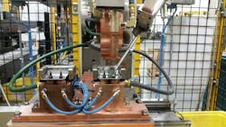
During the operation, a flanged nut is placed into position at the position to be welded. A welding gun ram is then lowered onto the nut and the position is checked just prior to welding to ensure the correct orientation. On occasion, the nuts would get placed upside down, with the flange facing upward (Figure 1). Historically the method that had been used to verify the nut orientation was to measure the stroke distance of the ram when it lowered onto the nut. If the nut was inverted with the flange up, the distance traveled would be reduced by approximately ¼ in to 3/8 in, and therefore the control system would know to reject and replace that particular nut prior to welding.
Figure 1: Paslin wanted to make it easier for both assembly workers and maintenance personnel to work on the machine, which meant transitioning to a different method for sensing the ram position and therefore the orientation of the nut.
Source: Paslin
“The machine as a whole uses a variety of sensors: proximity sensors for detecting the base part, air pressure and water flow sensors for validating the correct conditions prior to welding, as well as proximity for detecting the nut feeding cylinder and the status of the bowl feeder,” says Ron Pomaville, director of controls for Paslin. “The typical failure modes for the automatic nut feeder would be a missing nut, an upside down nut, a double nut, or a nut out of position. Using the stroke distance, the control system can determine if the gun is in the correct calibrated depth.”
Also read: How to get a better 'sense' with sensing
Historically, an LVDT had been attached to a fixed position on the machine frame and onto the ram of the machine in order to measure the stroke length. An LVDT is an electromechanical device used to convert the rectilinear motion of an object to which it is coupled mechanically into a corresponding electrical signal. LVDT devices typically use a nickel-iron core surrounded by primary and secondary windings to enable measurements as small as a few millionths of an inch.
While LVDT devices can achieve very high accuracy of measurement, they are mechanical devices and require a connection to both the fixed and moving portions of the machine. Paslin wanted to reduce the maintenance required on its machines due to environmental contamination and make it easier for both assembly workers and maintenance personnel to work on the machine. Obtaining this improvement, in part, meant transitioning to a different method for sensing the ram position and therefore the orientation of the nut.
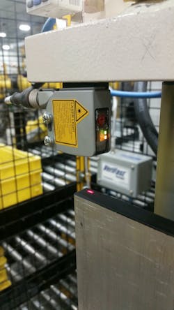
Figure 2: Paslin decided to eliminate the electromechanical LVDT device and replace it with a laser distance sensor mounted on the machine.
Source: Paslin
Several alternatives were considered. Paslin decided to eliminate the electromechanical LVDT device and replace it with a Balluff BOD 21M laser distance sensor (Figure 2).
“The new application of the sensor is for using an analog laser sensor for detecting the distance of travel the weld gun makes prior to the weld,” explains Pomaville. “It is also helpful in non-operator applications to signal the robot that the gun is clear and the robot can re-position the part. This sensor was chosen over previous versions with LVDTs. The sensor was cheaper, easier to mount, easier to set up and easier to maintain, and it could still protect against all failure modes.”
Advantages of the laser sensor over the previously used LVDT device was that it only needed to be mounted on one fixed point of the machine—mechanical adjustment was no longer necessary—and it was resistant to any environmental dust and contamination that may occur. These sensors are wear-free and are available with sensing resolutions down to 30 µm.
Interfacing the laser sensor required little modification of the control system, as they are available with a variety of analog output options to include the common 1-10 Vdc and 4-20 mA standards. The immediate advantages were in the initial setup of the machines. “The technical interface to the system is very similar—analog input 24 Vdc, for example,” says Pomaville. “The major difference was in the setup required. Since the switch was easier to mount and could be tested by placing an object in front of the sensor, it could be checked for linearity more easily than removing the LVDT mounting arms or having to measure approximate stroke.”
Light bar sensors
TGW Systems in Spring Lake, Michigan, is a manufacturer of automated conveyor equipment used to transport a wide variety of products. Their conveyor and sorting systems are used in food and beverage, manufacturing and production, and order fulfillment and distribution centers. Companies who use material handling conveyors are constantly looking for ways to improve the reliability and performance of their conveying systems. They typically are organizations that specialize in highly automated logistic or material handling solutions that demand adherence to tight shipping schedules and high throughput volume. Unscheduled downtime caused by equipment failures can be both costly and disruptive to the business operations.
Package sensing for conveyor systems has traditionally been accomplished with above-rail, over-the-conveyor photo eye and reflector systems that can sense a package or product moving down the conveyor line when it breaks the light beam. Photoelectric sensors mounted above the conveyors have been the standard for many years. It’s a proven system but has limitations on where it can be used.
TGW’s distributors and end users were looking for a way to increase the reliability of the conveyor sensing systems and reduce the need for maintenance. Above-rail sensors are typically not suitable for use with telescopic type conveyor systems. Telescopic conveyor sensors are typically embedded inside the railing system to provide the clearance needed to enable telescopic operations. There may not be enough clearance for the sensor bodies and cable to be mounted inside the side railing. Additionally the above-rail sensors have a difficult time sensing thin film items such as envelopes that may not present a large enough profile and so they go undetected.
Photoelectric sensors and reflectors mounted above the conveyor are prone to damage from the product being moved. The sensors and reflectors can be physically damaged by items such as loose garments coming down the conveyor and other material handling resources in the area. Other downtime events can be caused by sharp impacts to the sensor housing by objects being used to support the day-to-day warehouse activity. Conveyor vibration over time can also loosen mounting hardware, causing misalignment issues that add to downtime costs. The goal was to find a system to reduce all of these failure modes.
Figure 3: TGW decided to mount the photo-eye sensor between the rollers of the motorized roller conveyor system, thus eliminating the above-rail system.
Source: TGW
TGW decided to use a Telemecanique OsiSense XUY Roller Conveyor Sensor, which is mounted between the rollers of the motorized roller conveyor system, thus eliminating the above-rail system (Figure 3). “Being installed between the rollers makes it less subject to damage and misalignment, and it makes for a cleaner-looking installation,” explains Greg Braden, senior development controls engineer at TGW. “The system is very easy to install or retrofit, with no reflector needed.”
Having the sensor embedded in the conveyor between the rails eliminates the need for above-rail mounting hardware. This in turn eliminates damage due to product hitting the mounting systems and sensors and improves reliability. The XUY roller conveyor sensor can be configured with a variable number of photo eyes for full-width detection and does not require a reflector.
“Since the sensor is buried between two adjacent conveyor rolls, it virtually eliminates the physical damage that is common to above-the-rail-mounted photoelectric sensors,” says Allan Hottovy, business development manager at Telemecanique Sensors. “In addition, this sensor does not typically require mounting brackets, a reflector or any other specialized installation tool. Since the conveyor side rails are used as the mounting brackets, unscheduled downtime caused by loose or damaged mounting hardware is drastically reduced. Damage to the sensor components is reduced and life expectancy is extended.”
The application of the sensor allows for a clean-looking and reliable solution within any type of conveyor frame type, explains Tony Britton, technical support supervisor for TGW. “Whether it is TGW's CRUZchannel or C6 frame, the Telemecanique sensor works seamlessly within TGW's plug-and-play CRUZ-Logic controls framework."
Magnetic sensors
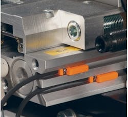
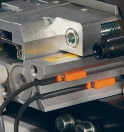
Figure 4: Magnetic sensors are used to sense the cylinder position as fully extended or retracted.
Source: Compass Automation
Compass Automation in Elgin, Illinois, designs and builds custom automation systems. It works in manufacturing processes across all industries focusing mainly on assembly automation and inspection automation systems.
It applies a magnetic sensor from IFM efector to pneumatic cylinders to measure stroke length. Compass also uses hydraulics and servos, but not with this sensor. Pneumatics are included on its product assembly machines, and the MK5328 magnetic sensors are used to sense the cylinder position as fully extended or retracted (Figure 4). They’re interfaced to an Allen-Bradley PLC.
“In order to build a successfully functioning machine, it is important to know the state of every actuator, and IFM’s sensors allow us to do this efficiently,” explains Bill Angsten, co-founder and executive vice president of Compass. “The mechanical engineering team equips every pneumatic actuator in our machines with at least two cylinder switches to provide the controls engineering team with all of the signals they need to write a properly functioning code.”
Angsten also appreciates the technical assistance that comes with the magnetic sensor. “One of the greatest advantages IFM has over its competitors is the accessibility to technical help,” he explains. “IFM has a wide database of almost every pneumatic actuator that we put on our machines, and they’re able to tell us which cylinder switches to use for each actuator. By having a set list of sensors to choose from, the mechanical engineer saves time in engineering the cylinder switch solution. This improves overall efficiency, which the customers will see in engineering cost. This efficiency is seen in every aspect of the machine, from the mechanical designing down to machine build and electrical wiring. The IFM products are also easy to install and adjust while on the machine, and their wide selection of cabling allows greater flexibility to our electricians in order to wire the machine as cleanly as possible.”
