A practical quick start guide for reliable machine vision applications
Key Highlights
- Successful machine vision integration relies on following a defined four-part process—preparation, design, implementation and deployment—rather than rushing into component assembly.
- To avoid costly delays, you should begin vision system development and physical prototyping immediately rather than waiting for the rest of the automation hardware to be built.
- Establishing a detailed scope of work and an acceptance test procedure during the design phase ensures the final system meets specific, measurable performance goals.
 DAVID DECHOW
DAVID DECHOW
MOTION AUTOMATED INTELLIGENCE
Machine Vision, Imaging, & Inspection
David Dechow, machine vision and automation solutions architect at Motion Automated Intelligence, will present "The Fundamentals of Machine Vision" at 8 am on June 22 during A3's Automate 2026 in Chicago.
You’ll learn all the basics, including how images are captured and transferred to the computer, the principles of lighting and the common processing algorithms used by machine vision systems. Discover how to successfully implement machine vision and how to avoid common pitfalls during the implementation, launch and production phases. This is an ideal training course for people new to machine vision, as well as a great refresher course for anyone with machine vision responsibilities.
Machine vision is well-established as an essential part of automation. Diverse vision technologies empower applications in a wide range of use cases, including quality assurance, metrology, assembly inspection and vision-guided robotics. The capabilities impact many industry sectors, reinforcing machine vision's significance in manufacturing.
Achieving consistent and effective results with automated imaging solutions though can seem challenging. Fortunately, for most any application a short list of practical steps, a “quick start guide,” can help ensure that machine vision systems deliver reliable and measurable results in automated processes.
The basics
Fundamentally, machine vision involves the implementation of systems in which images are captured—image acquisition—and then autonomously processed to obtain specific data—image analysis—and report the results for use in an automation process. It is this capability of extracting actionable information about an automated operation that makes it a significant and valuable technology in the concepts of Industry 4.0 and smart factories (Figure 1).

It’s understandable in the tech landscape that there can be confusion between the terms “machine vision” and “computer vision,” the former often described as using traditional tools and algorithms, and the latter using exclusively deep learning. However, while both have distinct capabilities, the steps to achieve broad practical application success are the same. That said, while acknowledging there are technical differences, this discussion will use the generic machine vision to cover all use cases.
Regardless of the exact technologies ultimately deployed in any system, there is a widely accepted process that can help ensure project success. The following quick start steps can be a practical guide that will help anyone at any level of machine vision expertise incorporate automated imaging.
The quick start guide
The job of bringing together diverse and disparate components and sub-systems and making them function as a single unified system is referred to in many disciplines as “systems integration.” The phases in the successful integration of a machine-vision application can be consolidated into four parts, each with a few easy-to-understand steps. These are:
- Part 1—Preparation: preliminary analysis and project requirements specification
- Part 2—Design: detailed final technical/system specification
- Part 3—Implementation: assembly/build/initial testing
- Part 4—Deployment: delivery/installation/startup and acceptance testing.
These integration parts/phases and functions might be described in different ways by different experts, but the one constant is that guaranteed success depends on following a defined process (Figure 2). Resist the temptation to dive right into the fun stuff—buying components, assembling the system and trying out tools. Just like unboxing and assembling that new chair for your home office, follow the quick start steps to ensure a successful implementation.

Part 1—Preparation
Consider the task of building a new house. It doesn’t start with ordering materials and getting out the tools. It begins with a complete understanding of the expectations and use and design requirements. With that information it is then possible to competently proceed with design and build. In the same context, this analysis and preparation phase is critical in machine vision projects. Here are the key steps.
Step 1. Undertake a formal and extensive application analysis. Analyze the needs of the existing operation, process or automation and how it might benefit from vision. Gather and document all the details relevant to the targeted application, for example:
- parts/objects related to the project, sizes, shapes, colors, variations, special characteristics, presentation
- incorporation with existing automation and physical, mechanical or environmental considerations
- commercial issues and limitations.
Step 2. Specify and document the performance requirements. Identify functions and operations—inspections, guidance, measurements—that are to be executed by the targeted automation along with the detailed related performance metrics. Prepare a requirements specification document that states what the proposed system must accomplish, and a preliminary acceptance criteria document that details how the system will be tested and validated.
Step 3. Develop a team. It’s important to recognize that integration in any discipline is a team activity. In machine vision the integration team must have skills in optics, lighting, electronics, controls, programming, mechanical design and project management and perhaps others like robotics, motion control, documentation and training. Be sure to keep a clear perspective that the overall system must enable the vision solution. Conceptualizing an automation system for a machine vision project with an empty box sketched in that says “put vision system here” is a guaranteed path to a difficult integration.
Part 2—System Design
A preliminary system design is based on the information gathered during the preparation phase. In this part of the integration, potential techniques and components will be considered relative to the project requirements and other project factors. There should be hands-on evaluation performed in advance to confirm that the proposed machine vision concept and components will be capable of meeting the needs of the requirements. The vision system design will also inform the requirements and constraints in the design of other aspects of the system.
The outcome will be a complete specification of the machine vision system, analysis techniques and related automation functions that will be implemented. In some cases, the design process will reveal technical or commercial limitations that might dictate changes to the requirements and overall expectations, and it is better to uncover these before implementing the complete application.
Step 1. Collect representative samples. Samples will be used for testing and ultimately for development. The samples must include all potential failure modes and part variations in scope for the project as detailed in the application analysis. For certain vision algorithms like deep learning, collect representative images in advance for training; it may require a very large number of images, and often these are best obtained in an actual production environment after the vision components are selected.
Step 2. Specify and select candidate components for imaging—in general terms, the camera, lens, lights and computer/software—based on the performance requirements collected in Part 1.
Camera: Key metrics for specification include at minimum the required number of pixels or image resolution and the required imaging rate. Image resolution is dictated by the spatial resolution necessary to achieve individual feature detection or measurement precision for the application and the overall field of view (FOV) needed to cover the objects or parts under inspection.
Note that the image resolution calculated for a targeted FOV might be so large that it is not practical or possible. Add more cameras or take other measures to achieve the necessary resolution.
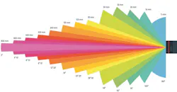
Lens: This optical component magnifies, or projects, an image the size of the desired FOV onto the camera sensor. Use manufacturer or third-party lens calculators to determine the correct focal length lens for the specified camera (Figure 3). For demanding applications, ensure the optical resolution in line pairs/mm is sufficient for the features to be detected. Specialty components like telecentric lenses might be considered for certain applications.
Illumination: Dedicated lighting is necessary for all machine-vision applications. Correct illumination delivers contrast between features of interest and the background to ensure repeatable and reliable imaging of the desired features. Experienced vision engineers may have an initial lighting technique in mind for an application, but in all cases testing and evaluation with the actual parts and specified camera and optics is a must to ensure proper performance. Seek out additional information on lighting techniques from manufacturers and other sources.
Get your subscription to Control Design’s daily newsletter.
Computers and software: The selection of these components drives the overall capability of the system by executing the key functions of image acquisition, analysis and data reporting. Decisions about the computing platform and software must consider the scope of the acquisition and analysis to arrive at an architecture that best serves the implementation requirements. Key metrics might include the speed of the process, the type and complexity of the machine vision tools that may be implemented and the type of interfacing required for an operator UI and for communication with external automation components.
Certain machine vision systems have the camera, computing and software in one package. These are generically called smart cameras. Other systems, which use separate cameras and computing components and often customized analysis code in some cases can be more flexible and have greater scalability.
Smart cameras are used in a distributed imaging architecture where one device is implemented for one imaging purpose. Computer-based systems can be more centralized, in that many cameras can provide images to be analyzed by one component.
Step 3. Evaluate the proposed system components. The candidate components and software always must be proven relative to the required application before committing to a final design and specification. In a practical sense, this also might come before providing a customer quote or otherwise committing to the project. As noted, this should be an iterative/repetitive step done in parallel with component selection.
Validate that the camera, optics and illumination selected will provide a repeatable and reliable image in the production environment. This will likely require multiple tries with different configurations and components to ensure the final design meets the application needs.
Check the image analysis using the selected computing platform and software with sample parts and the representative imaging components. Ensure it can meet the expected capabilities and return to the imaging design if there are problems.
Step 4. Prepare the final design, specification and scope of work. The final design defines the exact components, functional architecture and physical layout of the machine vision system. If a broader automation system is involved, that will of course be included but sometimes separate, depending on scope. A vision system specification details the way the vision system will execute the proposed tasks, including a more in-depth discussion of technical configurations and an overview of the tools and algorithms and how they will be used.
A scope of work (SOW) document is the ultimate outcome of the design phase. The SOW is both a technical and commercial statement of exactly what the system will do and the exact metrics to which it will perform. Note that the SOW might not exactly match the initial project expectations and desires. There will always be exceptions and limitations to initial requirements, and usually these compromises need to be resolved commercially.
Part 3—Implementation
Naturally, the systems integration process will turn from analysis and design to the acquisition of the components and materials and assembly, build, configuration and execution of the proposed system. This implementation may seem similar to any project, yet there still are some critical quick steps that will be useful specifically in machine-vision solutions.
Step 1. Create a detailed acceptance or validation test process document. Acceptance testing should not be an afterthought introduced at the end of a project. Based on the specifications and scope of work developed in Part 2, an acceptance test document should be prepared at the start of project implementation, or arguably before the start.
The acceptance test procedure becomes the defining document regarding functional and operational criteria and metrics that indicate the system is working to specification. Project engineers and managers must use this document throughout the process to ensure that both the machine-vision solution and related automation are built and configured such that the final system enjoys guaranteed success. It also helps to highlight problems earlier during build and configuration by revealing discrepancies that might ultimately impact system performance.
Step 2. Prepare a written project plan and task list. Project managers will agree with how critical this step is. If already being used, find one of the several good software tools available to help schedule tasks and manage projects. Use one to keep the project on track, but be sure to also address the details of the tasks, not just the timelines.
Step 3. Immediately prototype and begin vision system development. The most critical implementation mistake made repeatedly is to wait until an automation system, robot, mechanical components and controls are already built to start prototyping and development of the machine vision components and system software. While this step applies broadly to other sub-systems, it is critical to immediately start on the machine vision portion of the system as soon as possible.
Physical configuration of the imaging can easily be set up in a test environment using the many sample parts that should already have been collected and following the acceptance test requirements. Perform iterative testing of the vision system and automation throughout.
Step 4. For installation, refine, not design, online. While there are occasions where some imaging, process or program development must be done after online installation, this should be the exception rather than the norm. The most efficient and successful projects are complete, tested and validated prior to final installation. If possible, design and install the imaging components—camera, lighting optics—within the production environment early in the process to gather representative production images for further off-line testing and programming before final installation.
Part 4—Deployment
System delivery, installation, startup and on-site acceptance testing hopefully will be without incident if parts 1-3 have been followed and well-executed. It’s hard to argue against following the quick steps described above, yet almost every machine-vision engineer likely has been involved in a project that ends up on the plant floor not quite ready for prime time because some or all of the process has been bypassed. Presuming that is not the case, there still are a couple of quick start steps that will help in this phase.
Step 1. Communicate. Just as a rule, develop a good practice of communication, between project managers, cross-functional teams and customer or end-user teams. Frequent and detailed communications always facilitate a more successful deployment.
Step 2. Follow the validation plan. As mentioned, the written validation test plan should outline the functional and operational criteria and metrics that indicate the system is working to specification.
Depending on your discipline, industry and the size or scope of the application, systems integration may be approached in a wide variety of ways. However, no matter what the project is or whether you are working on a system for internal use or providing integration as a service, hopefully these quick steps will help ensure success.
About the Author
 David L. Dechow
David L. Dechow
engineer, programmer, technologist
David L. Dechow is an engineer, programmer and technologist with expertise in the integration of machine vision, robotics and automation technologies. Dechow has served various companies and most notably was founder, owner and principal engineer for two automation system integration firms. Dechow is a recipient of the Association for Advancing Automation (A3) Automated Imaging Achievement Award and is a member of A3 Imaging Technology Strategy Board. As an educator within the machine-vision industry, Dechow has participated in the training of hundreds of engineers as an instructor with the A3 Certified Vision Professional program. Contact him at [email protected].
Other articles by David Dechow include:
 Leaders Logo
Leaders relevant to this article: