From terminal blocks to smart cabling: Overcoming control panel constraints
Key Highlights
- Proper panel design requires strictly adhering to physical tolerances, heat limits and separation of high-voltage power from low-voltage control signals to avoid costly installation and maintenance issues.
- Advancements like tiered terminal blocks, push-in terminals, wire ferrules and preformed smart cabling systems significantly reduce panel size requirements and installation time.
- While software layout tools and wireless in-panel technologies offer new possibilities, practical physical constraints, such as wire bending radii, inductive interference and component reliability, remain critical factors in successful panel building.
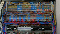
Panel wiring has always been a source of cost and overruns. It is important to understand the devices that happen to be in the panel. We have all seen pictures of bad panel implementation where distance tolerances have not been observed.
Heat issues, space and reflective/inductive voltages have always been a major consideration in panel design and implementation.
There are various electronic/software products helping with proper design on the panel backplate. The software takes into account things like tolerances, unless the designer decides to altar them to make things fit so the panel space doesn’t have to be expanded.
However, putting the cart before the horse can create many obstacles. I once worked on a project where the control cabinet had to fit in the space provided. It had to fit in between two motor control center (MCC) cabinets, which meant hat there wasn’t enough room for the required hardware.
The control transformer was relegated to the top of the cabinet, but the design still wasn’t ideal. The wireways were overstuffed because 3-inch had to be used and not 4-inch. Things like that create issues for installation, as well as the dreaded 3 am trouble call.
Part of the problem 30 years ago was the size of the control terminal blocks. The older blocks may have been 1/4 inch in size and thus took up more panel space than maybe they should have.
Terminal blocks take up so much less space now and are designed with tiered presentation allowances instead of linear applications.
There was always the wiring of the programmable logic controller (PLC) I/O to terminal blocks. As the I/O count increased the panel space seemed to grow by the square of the I/O points. The use of integrated voltages (dc/ac) requires the separation of wiring which creates a pathway issue. Trying to keep within the bounds of what’s proper becomes a challenge.
Wiring systems now can be employed where the PLC I/O has a preformed cable that connects to the I/O card and has a terminal solution on the end. I introduced Gus—for those who don’t know Gus, he is my son-in-law who is engaged in automation—to an in-panel wiring system for smart panel devices. He didn’t know about it, so I felt smart.
Not only does it not require terminal blocks as such, it does not require wireways as such either. It is low-voltage, so wire/ribbon cable placement is important, and you can’t use just anyone’s pushbuttons, of course. It saves install time and probably design time, as well. It sounds good, doesn’t it?
Get your subscription to Control Design’s daily newsletter.
Part of the advancements in panel construction revolves around the actual connectors. Every connection back in the day needed a screwdriver. European technology brought the push-in terminal and quick-clamp termination techniques. No more backing screws out in order to insert a wire whose strands invariably would fan out and leave a straggler behind.
This gave birth to wire ferrules, which made it easier to properly crimp the wire before mating it with a terminal block or connection on relay contacts.
It also gave the wire some stiffness at the connection point so the neatness of the install was maintained while the wire entered the wireway.
Control wiring and power wiring have different considerations. The incoming power source (480/600 V) required larger wire sizes. Depending on the current requirements of the panel, the wire size can cause significant inductive interference due to whether or not it is coiled.
High-current motor starters typically will be located in the MCC somewhere, but on occasion a 10-hp starter could be in the control panel. Wire bending radius has to be observed, which complicates the install.
There has been talk of Bluetooth-enabled devices. Process instruments have been for a while, but devices like panel-mounted buttons and lights may get priced out of the market since you would need an interface to congregate the devices into a single hardware solution. Trust might also be an issue; wireless technology inside a panel would encounter lots of interference due to voltages.
Some of these devices use energy harvesting to power themselves, but I would not rely on this technology to be sure a process stopped when pushed. Call me old-fashioned.
One thing that hasn’t changed in panel wiring design and implementation is that there are a plethora of panel builders who can create a piece of art from a piece of paper. Hole drilling layouts, cutouts and proper tolerances are all part of the solution. In the past five years, it may have changed, but the tried-and-true terminal block and screwdriver may are still around.
About the Author
 Jeremy Pollard
Jeremy Pollard
CET
Jeremy Pollard, CET, has been writing about technology and software issues for many years. Pollard has been involved in control system programming and training for more than 25 years.
 Leaders Logo
Leaders relevant to this article: