How to bridge the gap between safety devices and protocols
Key Highlights
- Instead of running dozens of individual cables from field valves back to a central enclosure, it is far more practical to aggregate safety data locally using decentralized IO-Link safety hubs.
- Even though Studio 5000 doesn't natively speak Profinet/ProfiSafe, you can successfully route safety data to a Rockwell PLC using hardware gateways or multiprotocol masters combined with proper data validation in the logic.
- Achieving strict standards like ISO 13849-1 self-monitoring or a SIL 3 rating requires rigorous data mapping, precise configuration files (GSDML/EDS) and true component redundancy rather than simple, single-channel solutions.

Integration problems come in different packages. What if you have 76 valves that you need to make safety-rated for the purpose of meeting a safety requirement, yet the integrator wants you to wire all the valves back to a cabinet or two?
It seems it would be more practical to wire the stands to a local remote input/output box and then send the data over Ethernet. The integrator will fuss and say that you cannot do CIP Safety that way. Why? ProfiSafe has been doing it for a while.
IO-Link safety devices are designed for and communicate natively over Profinet/ProfiSafe. Rockwell Studio 5000 does not communicate natively with Profinet/ProfiSafe. What is the fix? IO-Link has a master that supports both ProfiSafe and EtherNet/IP for the Rockwell suite. Otherwise, a gateway is needed to work in between, but is this still safe? Festo’s IO -Link master has been successful. There are also multiprotocol masters that can receive/transmit for IO-Link data as a safety hub and act as an EtherNet/IP adapter to communicate to a Rockwell PLC.
What are the options for communicating ProfiSafe to Rockwell PLC?
- Use a hardware gateway with a Profinet I/O slave and an EtherNet/IP adapter/scanner on the other side.
- Install a Profinet module in the Rockwell chassis to allow the Rockwell PLC to be the Profinet master.
- The third option is to use a fieldbus independent cross-platform controller. These type platforms use a safe link technology (Figure 1).
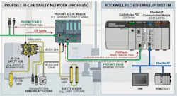
Figure 2 shows an example with Anybus.
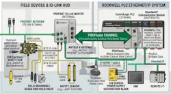
In this integration, ifm IO-Link masters collect the ProfiSafe safety data from the field valves via orange M12 ifm connection cables. The data is then transmitted through the following path:
- The hub: An ifm IO-Link Safety Hub, or safety-rated master, monitors the hydraulic valve feedback.
- The bridge: An Anybus X-gateway acts as a Profinet I/O device to receive the safety data from the ifm master and translates it into EtherNet/IP for Rockwell PLC.
- The PLC: Rockwell’s ControlLogix PLC receives the data as standard Ethernet packets and processes the safety logic through specialized add-on instructions (AOIs).
To make it work safely, the controls engineer would configure the Anybus gateway using the Anybus configuration manager, set up the I/O sizes, internally map the I/O so that the first byte of Profinet data matches first byte of Ethernet data.
Get your subscription to Control Design’s daily newsletter.
Then the controls engineer would configure the Profinet side as the scanner/master. This involves downloading a general station description markup language (GSDML) file and importing it into the Profinet configuration tool. At that point, the I/O modules on the gateway need to match the hardware configuration byte sizes set up initially.
Next, the Rockwell side of the architecture would have to be configured. This is done by adding a new module as an Ethernet bridge into the tree. Use a generic Ethernet module. Set up the connection parameters to match the configuration: communication format (DATA SINT (8 bits)), input assembly of 100, output assembly instance of 150 and configuration instance of 1.
Afterward, the safety data must be decoded in the safety PLC. Anybus transmits a ProfiSafe telegram that arrives at the Rockwell controller as an array of short integers (SINTs). Rockwell programmers can do COP instruction and move the raw SINT data into a user defined tag (UDT) that matches the ProfiSafe structure. Then using cyclic redundancy checks (CRCs) and watchdog timers, the safety data can be validated.
Note that GSDML files are equivalent to electronic data sheet (EDS) files in Ethernet land. Fortress and the like include EDS and GSDML files with their safety components. Emerson, Endress+Hauser, Spirax Sarco, SMC and others provide GSDML files for valves and actuators that can be used in a safety configuration.
Thus, what if your valve stand does not have safety valves? Then you monitor inputs going into a safety PLC and use dry contacts or output signal switching with dedicated safety relays like the Rockwell GuardMaster Safety Relay (GSR).
Another way to look at it is Figure 3.
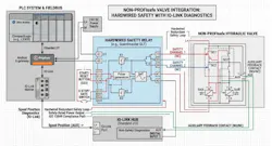
The objective of this configuration is that you can hardwire feedback while monitoring the IO-Link to provide the ISO 13849-1 standard of self-monitoring. As you may see, the safety system concepts are not simple, which leads to increased costs. It’s imperative to have an integrator provider that you trust. Thus, be careful when someone says they can sell you a SIL 3-rated circuit. SIL 3 would require redundant monitoring and SIL 3-rated components.
About the Author

Tobey Strauch
Arconic Davenport
Tobey Strauch is currently managing brownfield installations for controls upgrades at Arconic Davenport. She has previously worked as principal controls engineer and before getting her bachelor’s in electrical engineering, was a telecommunications network technician. She has 20 plus years in automation and controls. She has commissioned systems, programmed PLCs and robots, and SCADAs, as well as managed maintenance crews. She has a broad mix of mechatronics with process control. She enjoys solving problems with Matlab and Simscape. Contact her at [email protected].

Leaders relevant to this article: