Key Highlights
- Terminal blocks serve as critical connection and segmentation points that distribute power, route signals and protect expensive PLC cards from field shorts or wiring faults.
- Choosing the correct connection mechanism—such as tool-free push-in styles for speed or spring clamps for high-vibration areas—depends entirely on the specific demands of the industrial environment.
- Integrating smart or fused terminal blocks with diagnostic lights accelerates troubleshooting, and combining them with IO-Link communication protocols unlocks precise device-level feedback and automatic reconfiguration capabilities.
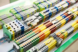
A terminal block is a place to connect a wire to another wire and create a junction point. Picture a terminal block as an intersection on a two way or four-way highway.
Terminals may be required because the wire got short, the wire needs to have a condition or there is protection required. Automation uses and machine building uses terminal blocks for signal and power distribution, as well as grounding. Terminal blocks may be integrated with a fuse for isolation. Terminal blocks may have integrated relays. Terminal blocks may have multiple levels or withstand high currents. Terminal blocks may be push-pull, plug in, screw types or clamps.
The possibilities are endless when it comes to terminal blocks. Push-in blocks may allow tool-free insertion and faster wiring, but high-vibration environments might work better with a spring clamp block. Screw terminal blocks may come undone with vibration or get over-torqued. Choosing what types of terminals may be dependent on the application. Typical automation panels will have ground terminal blocks, power distribution blocks, fuse terminal blocks, PLC I/O terminal blocks, relay terminal blocks or disconnect/test terminal blocks.
The terminal blocks may use colors to denote signal types. For instance, green blocks may be used for grounding; white for commons; and blue for 24 Vdc. Field connection boxes may have feed-through blocks, though most remote inputs or outputs may be installed so that signals may remain local before going to the main PLC chassis.
What is the best approach for describing terminal blocks in the field? If one takes the view of the electrician doing the terminations, then it’s literally a three-column table with the to cable number, the terminal block number and the from cable number may suffice. This would allow the technician to print the wire labels for the cables being installed, as well as have a reference sheet for terminations in the field. Small drawings showing terminal block screws are not practical in industrial environments.
Some newer versions of terminal blocks are fused and have indicator lights. The blocks are normally DIN-rail mounted and have thin housing for low-voltage connections. Why might a fused block be used? Fused blocks may be used for protection of input cards or for enhancing troubleshooting. Green lights mean good. Red light or no light means bad. Fused blocks may also isolate other circuits from being affected. For instance, solenoids are notorious for shorts. How does a controls engineer protect the PLC cards from a solenoid short? Bring them in fused terminal blocks with a normally open status.
Get your subscription to Control Design’s daily newsletter.
What if all the fancy stuff is not necessary and a 24-V dry contact is needed for a starter circuit. Basically, if the contact is turned on by the PLC output, then send 120 Vac to start a motor. This is not a problem. But what if the wire breaks? Having the panel configured with terminal blocks between the PLC and the field allows for a segmented wiring approach for signaling and protection for the PLC cards. PLCs are more expensive than terminal blocks.
With the onset of more functional safety in machines, monitoring wire breaks is important. This is not a new concept. It’s a review of Ohm’s Law and applied electronics. IO-Link has made it more common for terminal block aptitudes. However, the IO-Link block is not a typical terminal block, but it still meets the idea of an input with a transition point and an output.
For hydraulic monitoring of pressure or pneumatic feedback via a hub, IO-Link can not only provide signals back to the PLC, but it can provide data, power and diagnostics to a master block. It also allows drop-in replacements of devices. If the device breaks, then the IO-Link network can download the parameters to the new device when the M12 is plugged in to the new one. Short circuits and cycle logs are not an issue for components on IO-Link.
What is the difference between a smart terminal block and IO-Link? IO-Link is a communications technology with protocols. Smart terminal blocks are hardware. What makes an awesome duo is a smart terminal block on an IO-Link system (Table 1).
Is IO-Link necessary with smart terminals? No. All these design options are dependent on the application and the customer needs. Sometimes the added costs of adding the IO-Link capacity are too much. However, adding smart terminal blocks that allow maintenance personnel to see a problem briefly when opening the cabinet, or when providing feedback to an HMI status page, may assist in troubleshooting. Software connecting to an IO-Link master station can also provide system feedback down to the conductor level as well, but it would require software and plugging into the network.
About the Author
 Tobey Strauch
Tobey Strauch
Arconic Davenport
Tobey Strauch is currently managing brownfield installations for controls upgrades at Arconic Davenport. She has previously worked as principal controls engineer and before getting her bachelor’s in electrical engineering, was a telecommunications network technician. She has 20 plus years in automation and controls. She has commissioned systems, programmed PLCs and robots, and SCADAs, as well as managed maintenance crews. She has a broad mix of mechatronics with process control. She enjoys solving problems with Matlab and Simscape. Contact her at [email protected].
 Leaders Logo
Leaders relevant to this article: