How to demystify triangulation, structured light and time-of-flight for vision sensing
Key Highlights
- 3D machine vision has evolved from complex, custom-built systems into factory-calibrated, integrated sensors that easily keep pace with production line rates by outputting ready-to-use point clouds or depth maps.
- Except for time-of-flight and LiDAR, most industrial 3D imaging techniques rely on triangulation, which uses a physical baseline between components to calculate depth but introduces tradeoffs regarding spatial resolution and object occlusion.
- By capturing depth data and six-degrees-of-freedom pose information, 3D vision solves complex automation challenges that 2D systems cannot, including bin picking, non-contact CMM measurements, flexible part assembly and mixed-object logistics.

PERRY WEST
AUTOMATED VISION SYSTEMS
Machine Vision, Imaging, & Inspection
Perry West, president, Automated Vision Systems, and David Dechow will lead the Certified Vision Professional (CVP) course "Vision System Design" at 10:30 am on June 24 during A3's Automate 2026 in Chicago. The value of any machine vision technology lies in the successful implementation of a systems solution for a task in an automated process. The knowledge gained in cameras, lighting, optics and image processing is the foundation for successful design of a working machine vision system. In this course, you will learn the role of machine vision systems design in the broader task of systems integration and the general steps and strategies involved in the design of a vision system, including selection of components in typical use cases, and specification of the implementation of those components. The information provided will enable you to participate in and support a team delivering practical machine vision to plant floor automation.
West also will lead the "High-Speed, Real-Time Machine Vision" course at 3:30 pm on June 22. This course gives the insights to achieve the speed and performance needed in vision systems, including system architecture, programming tips and common challenges. You will understand the ways high-speed is determined and the different real-time performance requirements. The course follows two vision system designs to see how high-speed and real-time techniques are put into practice.
Although machine vision emerged using line-scan (one-dimensional) and area (two-dimensional) imaging, it was apparent from the earliest moments that many applications needed 3D imaging. The holy grail of applications was bin picking, which not only required advances in mechanical sophistication but also improved 3D imaging.
There are true 3D imaging techniques, such as computed tomography that provide information about all points in a volume. In most cases today, 3D imaging provides information about the shape of a part’s surface. Occasionally, this is called 2½D imaging.
3D imaging not only requires techniques different from 2D imaging, but also requires image processing techniques that differ in many respects from 2D imaging. Interestingly though, almost all 3D imaging techniques use one or two 2D cameras.
Evolution
Even at the beginning of machine vision, we had stereo imaging and simple structured light using a single stripe of light, now commonly called laser profilometry. Developers envisioned using more complex structured light patterns to cover an area, but they were static. The computational burden of processing 3D image data made most industrial applications infeasible. Also, people wanting to use 3D imaging needed to build their own imaging systems from multiple devices and write their own software from scratch.
The situation has changed. Instead of a developer needing to design and build their own 3D sensor and write the code to interpret the 3D data, there are now fully integrated 3D sensors that usually include embedded code or a software API to provide a calibrated point cloud or depth map.
Computational power has increased to the point where 3D imaging can easily keep pace with production rates. There are many suppliers of 3D imaging devices ready for industrial use.
Calibration
Integrated 3D sensors are typically factory-calibrated for their intrinsic parameters. After intrinsic calibration, the sensor is able to provide 3D data in relation to itself. Extrinsic calibration, which transformation from camera to world coordinates, must be performed after the 3D sensor is installed.
Because intrinsic calibration is set at the factory, there is no ability to make any physical changes to the 3D sensor itself, such as changing lenses.
Techniques
Many people differentiate 3D techniques as either passive or active. Active 3D techniques have a light source that is integral to depth sensing. In passive 3D techniques, the light source is not critical to depth sensing. Stereo vision is the only passive 3D technique used in machine vision. The distinction between passive and active is important in military reconnaissance and surveillance, but not in machine vision imaging.
Another distinction is whether or not triangulation is used. All machine vision 3D imaging techniques except time-of-flight (TOF) and light detection and ranging (LiDAR) use triangulation. In triangulation two or more components, camera or light source, are separated from each other by a baseline. The distances from a point in the scene to each component along with the baseline form a triangle. Through calibration, the triangle allows calculation of distance from the sensor to the specific point in the scene.
In triangulation, increasing the baseline increases the resolution of distance. However, the baseline makes it possible for one component to access features in the scene that are occluded from the other component. A larger baseline increases the potential for occlusion. Where occlusion occurs, the triangle cannot be completed, and the sensor will not return distance information.
Here are the more common and available 3D imaging technologies.
Laser line profilometry
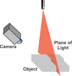
In laser line profilometry, a narrow plane of light, usually from a laser, is projected onto the scene. A 2D camera images the line created at the scene’s surface at an angle as shown in Figure 1. The displacement of the line in the camera’s image gives the height of the surface at every point along the projected line.
Laser line profilometry offers high accuracy, down to the micron level. However, it provides only a single 2D profile for each image. To create an entire 3D profile, the part must move under the sensor or, less commonly, the sensor must move over the part.
Stereo imaging
Stereo imaging uses two 2D cameras imaging a scene from different angles (Figure 2). The two cameras are calibrated together for intrinsic parameters after being securely mounted together. By identifying corresponding features in the images from the two cameras, the difference in location of the features in the two images, called disparity, provides the distance from the cameras to the features.
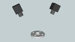
A key advantage of stereo imaging is that both cameras capture images simultaneously, enabling snapshot 3D imaging. However, it can only determine depth for features present in both images. Smooth surfaces, which lack identifiable features, do not provide depth information.
Augmented stereo
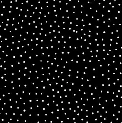
Augmented stereo imaging uses the same two cameras as regular stereo imaging plus a projector that projects a pattern, usually a pseudo-random dot pattern similar to what is shown in Figure 3, onto the scene. The dots provide optical features on smooth surfaces that enable the stereo imaging system to detect them. This overcomes a shortcoming of regular stereo imaging.
The density of 3D features and points in the point cloud is limited by the density of features in the projected pattern.
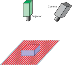
Patterned structured light
In patterned structured light, a single 2D camera, along with a projector projecting a pattern onto the scene, is used as shown in Figure 4. It is a simplification of augmented stereo by using only one camera. In the case of patterned structured light, the camera and light source are calibrated together for intrinsic parameters after both are securely mounted together. Like with augmented stereo, the density of 3D points is limited by the density of features in the projected pattern.
Binary structured light
Binary structured light uses a 2D camera and a projector. The projector projects a series of black and white lines onto the scene, starting with very coarse lines and ending with very fine ones. The camera and projector are calibrated after being securely mounted together.
Binary structured light provides high-quality 3D data but requires many images to get high resolution.
Gray-scale structured light
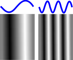
Gray-scale structured light uses a 2D camera and projector, similar to binary structured light, with the projector illuminating the scene with a varying-intensity pattern, typically a sinusoid pattern as shown in Figure 5. The camera and projector are calibrated together after being securely mounted. Several patterns, usually three, but sometimes more, are projected and imaged. Using gray-scale correlation between the patterns, depth information is extracted. Gray-scale structured light provides very dense depth information with fewer images than binary structured light.
LiDAR
Light detection and ranging (LiDAR) is a time-of-flight technique where a light pulse, usually from a laser is projected outward and the time between the light pulse’s transmission and the detection of a return signal is measured (Figure 6). Knowing the speed of light, the distance to the surface that reflects the light is determined.
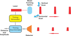
Since LiDAR emits single light pulses, it must be scanned. Usually, scanning is done mechanically. A LiDAR imager might contain multiple emitters and detectors working simultaneously on different parts of the scene to speed up image acquisition.
LiDAR excels at measuring long distances due to its focused, narrow laser beam. However, it is often slow in generating 3D images because of the mechanical scanning and typically produces sparse 3D data to balance speed and data density.
Time-of-flight (TOF) imaging
Time-of-flight imaging, sometimes called flash LiDAR, consists of a camera with a specialized image sensor. This image sensor has pixels that each measure the time between when the light pulse leaves the camera until it returns.
There are two techniques for time-of-flight imaging: direct and indirect.
In direct time-of-flight imaging, illustrated in Figure 7, the camera emits discrete light pulses to illuminate the whole scene. The pixels on the image sensor have the ability to measure the time between emission of the light pulse and when it is sensed by the pixel. Indirect time-of-flight, illustrated in Figure 8, uses continuous amplitude modulated laser light to illuminate the scene. The pixels measure the phase difference between the emitted light and the received light to determine the distance.
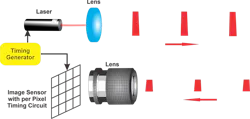
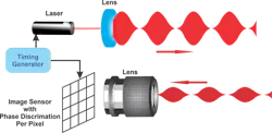
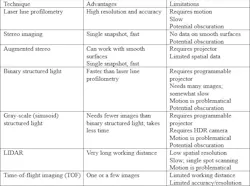
Table 1 lists common 3D imaging techniques and their advantages and limitations.
Bin picking
There are quite a few areas where 3D imaging is either essential or provides substantial improvements over traditional 2D imaging techniques in industrial automation. One of the most prominent examples is bin picking, a task that involves selecting randomly oriented and overlapping parts from a container. Once considered the holy grail of machine vision, bin picking remained largely unsolved for many years due to limitations in both sensing and robotic control. The emergence of practical 3D imaging technologies, combined with advances in robot motion planning and control, has transformed this application into a viable and increasingly common solution.
Get your subscription to Control Design’s daily newsletter.
Unlike 2D imaging, which captures only flat, intensity-based information, 3D imaging provides depth data that allows robots to understand the spatial arrangement of objects within a bin and the pose in all six degrees of freedom of each part. This pose information is critical for determining how a robot must reach to grasp a part accurately.
Measurements
Making precision measurements where height or surface variation is critical is greatly facilitated by 3D imaging technologies. Traditional 2D imaging methods are limited to capturing planar information and cannot reliably quantify vertical deviations, making them insufficient for applications that require tight tolerances. Among 3D techniques, laser profilometry is the most widely used for high accuracy. By projecting a laser line onto a surface and analyzing its deformation in the captured image, this method can reconstruct detailed surface profiles with precision reaching into the micron range. This level of accuracy is essential in industries such as semiconductor manufacturing, precision machining and electronics assembly, where even minute deviations can impact performance or yield.
In addition to standalone measurement tasks, 3D vision systems are increasingly integrated with coordinate measuring machines (CMMs) to enhance their capabilities. Traditionally, CMMs rely on tactile probes that physically contact the part, which can be time-consuming and may introduce wear on both the probe and the component. By incorporating non-contact 3D imaging, these systems can perform high-precision measurements more rapidly and without risking damage or tool degradation. This not only improves measurement speed but also maintains long-term accuracy by eliminating probe wear. As a result, manufacturers benefit from more efficient inspection processes and more consistent quality control.
Assembly
3D machine vision has significantly expanded the possibilities for robotic assembly by enabling accurate identification of a part’s pose in all six degrees of freedom—three translational and three rotational axes. This capability allows robots to understand not just where a part is located, but also how it is oriented in space. As a result, the reliance on rigid fixturing and specialized tooling is greatly reduced, since parts no longer need to be presented in highly controlled positions for successful handling and assembly.
With 3D vision, even the assembly of flexible or deformable components, such as cables, gaskets or soft materials, becomes far more practical. These parts often vary in shape and position, making them difficult for traditional 2D systems to handle reliably. By capturing depth and surface information, 3D systems allow robots to adapt in real time to these variations.
Reducing the need for custom tooling and fixtures also leads to faster setup and changeover times, which is especially valuable in high-mix, low-volume manufacturing environments. This flexibility translates directly into higher productivity and lower operational costs. Additionally, 3D vision systems are better equipped than 2D systems to compensate for small variations in part geometry and placement, thereby maintaining tight tolerances during assembly and improving overall product quality.
Inspection
Complex assemblies are almost always three-dimensional in structure. Inspection of these assemblies requires 3D data. While this can sometimes be accomplished with multiple 2D images and sensor fusion, this 2D approach is often not practical. For example, if the inspection is to verify PC board assembly, knowing that components are flush with the board and not raised or tilted, even a small amount, is essential to being sure the assembly will be reliable. In automotive assembly, knowing that a seat is installed correctly is a three-dimensional problem that cannot be solved with 2D imaging.
Logistics and warehouse automation
In an automated distribution warehouse, products being delivered to fill an order typically vary widely in size, shape and rigidity. Some items arrive in rigid packaging like boxes or cartons, while others are soft, deformable or irregularly shaped, such as polybagged goods, apparel or food items. This variability poses significant challenges for robotic handling systems, especially when the goal is to assemble mixed orders efficiently and reliably.
To achieve high throughput and accuracy, the system must first determine the exact location and orientation of each item, whether it is moving along a conveyor belt or sitting in a bin or tote. This requires more than simple 2D imaging, since height, depth and surface geometry are essential for understanding how to grasp and manipulate an object. 3D imaging technologies, such as stereo vision, structured light or laser-based depth sensing, generate point clouds or depth maps that capture the full spatial structure of each item.
Once each product’s position and orientation are known, robotic systems can plan grasping strategies and determine optimal placement in shipping containers. Packing efficiency becomes a spatial optimization problem, requiring items to be arranged for maximum space utilization and minimal risk of damage. Real-time 3D perception is essential for accurate identification, reliable picking and efficient packing in automated warehouses.
Palletizing and depalletizing
Objects placed onto a pallet must be positioned securely, or the contents of the pallet will shift during transport. 3D machine vision helps ensure that all containers on the pallet are nested securely next to their neighbors.
Depalletizing can be even more challenging. Containers on the pallet may have shifted during transport. The pallet may contain mixed objects of different sizes and shapes in an unknown arrangement.
To automate each of these operations with a robot, 3D machine vision is necessary. For palletizing, the vision system can accurately detect exactly where the next container must be placed to nest securely. For depalletizing, the location of each individual container is located, even if it is different from its neighbors.
Other applications
The list of applications for 3D machine vision is very lengthy. Some other applications not mentioned above are object recognition and sorting, reverse engineering and machine tending.
Conclusion
3D imaging is an important capability in machine vision system development. A number of different imaging techniques give the user choices of speed and accuracy as well as cost. The growing availability of integrated 3D sensors and software to work with 3D data facilitates a variety of applications and makes this capability an established factory automation technology.
About the Author

Perry West
Automated Vision Systems
Perry West has led Automated Vision Systems as president for more than 45 years. Contact him at [email protected].
Other articles by Perry West include:

Leaders relevant to this article: