How to troubleshoot 4-20 mA analog control loops
Key Highlights
- Control systems rely on discrete and analog circuits to connect field instruments like transmitters, actuators and valves to PLCs and HMIs.
- Signal errors and 4-20 mA loop failures stem from various factors, including high loop resistance, improper grounding, wiring mismatches and component faults.
- Circuit troubleshooting requires a systematic, step-by-step approach, segmenting the loop, using multimeters to inject or measure signals and applying Ohm's Law to isolate failures logically.
Control systems may have many types of circuits. The two primary circuits used in process are discrete and analog circuits. Discrete circuits are normally on or off and have a discrete response matching to buttons and switches. Analog circuits may be current based with 4-20 mA or voltage based with 0 to 10 V.
When an analog circuit fails, then electricians typically troubleshoot, but electrical engineers will also get called to validate the circuit. Plant operators monitor pressure transducer inputs, levels or motion feedback circuits such as actuators and valves. These are some common transmitter types.
A 4-20 mA loop failure can be indicated by many things.
- Unusual process conditions can cause a report of a fault to the maintenance team. In upset conditions, the instrument can be reading correctly, but something process-related is causing the non-normal indication. If an instrument falls out of calibration, it can also indicate an abnormal reading.
- High loop resistance would mean that the transmitter would have trouble maintaining a current signal at a correct level. This would cause inaccurate readings, as well.
- Scaling mismatches between the human-machine interface (HMI) and programmable logic controller (PLC) can also cause inaccurate readings.
- Field component failure can show as an open if the instrument in the field is no longer completing the loop and sending an indication back.
- PLC card failure could cause an incontinence if the port fails or the card fails. If this is true, then one would expect an abnormal condition on more than one circuit.
- Cut wires or broken wires would cause opens that can be tested by “ringing” out the loop and checking resistance.
- A power mismatch for the bus powering the input card could also show across more than one circuit. Polarity needs to be validated at the transmitter, power supply and the input device. Input loops are typically powered from the input card bus.
- Power failure based on fuse failure. Excessive current is a symptom not a cause.
- Grounding can also cause issues.
- Wiring mismatches can be found if terminal landings were incorrect and someone split the transmit and receive between two circuits, which means the loop would appear to work but the reading would be from the neighboring field device.
- Losses can occur if the shielding is not wired correctly and the circuit is in a noisy environment.
Get your subscription to Control Design’s daily newsletter.
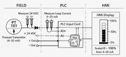
What does a 4-20 mA circuit look like? There are three parts to an analog circuit, and there is typically a source (+24 V), a common (-24 V) and a shield wire. A traditional circuit has the field device (1), the wiring from the field device to the terminal block (2), the terminal block to the PLC input or output (3). A remote circuit may just be from the field to a remote input/output card rack and then an Ethernet connection to the main controller. Also, the HMI will read from the PLC, and some may consider that a fourth part of the circuit since the software may cause an inaccurate reading. An example of an ISA type sketch is pictured in Figure 1 with locations to test.
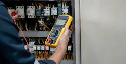
One way to troubleshoot is to remove the instrument and use a multimeter device that can generate a 4-20 mA signal back to the PLC. These instruments are used to check the loop wiring and the PLC input card and to tune PIDs in the PLC.
Another way is to use a multimeter in series to measure the current and then have an operator generate a signal by asking for a low, mid and high range signal that translates to the 4 mA, 12 mA and 20 mA readings. Once that is validated without the device, it can be said that the field device is failed. If the field device is reconnected and the physical locations just don’t match the 0, 50, 75 and 100% positions, then the device or PID loop needs to be calibrated. There are also mA clamp meters that are valuable for commissioning many circuits.
Otherwise, when the transmitter device in the field is removed from the circuit, testing the loop should give indications to the symptoms described above. Breaking the circuit into pieces, for example, PLC to the terminal block, terminal block to the field device, allows a segmented approach that can be done systematically so as not to waste time. Using proper tools like a multimeter and understanding that one must be in series to measure current or convert the voltage readings to expected mA will help. The other part is understanding what the components in the field are actually calling for. Understanding the type of current loop transmitters that may be in a field component can help. Along with this, knowing that the circuit is powered properly will ensure good signal. It never hurts to review basics, and basics for controls engineers is Ohm’s Law. Understanding Ohm’s Law and how the current transmitter works allows an engineer to build a base so that they can look at a circuit objectively and not from a shotgun troubleshooting approach. It is imperative to pick a side of the circuit and work field to PLC or PLC to field, depending on the symptoms generating a fault, document findings and then make a decision based on facts, not opinion.
About the Author
 Tobey Strauch
Tobey Strauch
Arconic Davenport
Tobey Strauch is currently managing brownfield installations for controls upgrades at Arconic Davenport. She has previously worked as principal controls engineer and before getting her bachelor’s in electrical engineering, was a telecommunications network technician. She has 20 plus years in automation and controls. She has commissioned systems, programmed PLCs and robots, and SCADAs, as well as managed maintenance crews. She has a broad mix of mechatronics with process control. She enjoys solving problems with Matlab and Simscape. Contact her at [email protected].
 Leaders Logo
Leaders relevant to this article: