How to split 4-20 mA signals when running PLCs in parallel
Key Highlights
- Running old and new PLCs in parallel allows integrators to shadow real-world inputs and validate new control software before the new PLC takes control of the process.
- A signal splitter can provide isolated 4-20 mA outputs to two PLCs, allowing one side of the circuit to be decommissioned without breaking the other PLC’s signal.
- Wiring PLC inputs in series can be less expensive than using a splitter, but the shared power and common connections can complicate troubleshooting and cause the entire circuit to fail when one PLC is disconnected.
When installing machines, there are instances when integrators might want to run a new programmable logic controller (PLC) parallel to an old PLC. Integrators do this to get real-world inputs and shadow a process. This means adding a temporary rack and splitting analog inputs between racks and making the outputs testable with pinned terminal blocks.
At one point, the new PLC will be ready to take over the process, and, at that time, decommissioning of the circuits should happen. Or, if there is a time for the customer to become comfortable with the new PLC, then decommissioning of a panel may happen while running at a later time.
However, if the analog circuits are not split properly for the inputs to both PLCs, then decommissioning could result in a failure. Thus, the options are to wire it to only be decommissioned on a down day or wire the new panel to allow decommissioning without a down day by isolating inputs and outputs. Outputs won’t be discussed here, since, they are just split on terminal blocks because control can only be from one PLC. Inputs can be split and sent to two PLCs for monitoring.
Current loop circuits in series occur in many machines. Process control sees it often. Why would we do this? The simple answer is that there is a requirement for the signal to go two places. One thing that should be understood when doing so in isolated circuits is what the common is.
In an electrical circuit, the common is the shared electrical connection that serves as a reference point or return path for multiple components or signals, although its function depends on the type of circuit.
Use isolated terminal blocks any time you need to terminate, organize or protect wiring without electrically tying circuits together. Isolated blocks are one of those deceptively simple components that quietly solve a lot of real-world control panel problems. If a circuit is being split and it’s not isolated, then it can cause confusion.
Confusion would arise around the common. The electrical common on a 4-20 mA loop circuit refers to the shared reference from the power supply. The common is the return path for current in the loop — the point where all connected devices share the same electrical potential.
It’s typically the negative terminal of the 24 Vdc supply or the low side of the loop. Either way, if you are shadowing an old system with a new PLC, and want to share inputs, the common has to be shared, as well.
Get your subscription to Control Design’s daily newsletter.
What are the options if you want to receive one signal from a field transducer and see the signal in two places? Current loops guarantee noise immunity, long cable runs and consistent measurement, regardless of wire resistance. Putting devices in series preserves the “same current everywhere” property.
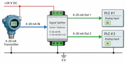
Isolation means keeping wire properties separate at the terminal block to make sure there is no noise or common issues or shorts to ground. The best way to keep the circuit isolated is to not share commons and to use a splitter. Installing a splitter requires an external 24-V power supply, but this will be needed anyway (Figure 1). Each output from the splitter can have an isolated source and common. That way, if the one side of the circuit needs to be decommissioned, the whole circuit does not break.
The second option is to wire the inputs in series, where the input from the transducer in the pressure sensor goes to PLC1 and then the return is fed into PLC2 (Figure 2). The pros to this option are that it does not cost a lot. As you can see though, the commons and the positive Volts must be shared. This means that if you take away one PLC connection on decommissioning, then the whole circuit fails.
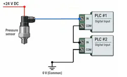
For brownfield options, Figure 2 may be tricky since the terminal blocks could be in the same location as where you want to install a new cabinet. It also makes it difficult to troubleshoot if someone accidently takes your common and no one documented the extra terminals.
If you are installing a machine, then what is the tradeoff between the two options? First, when managing the construction, determine if the two PLCs have to continue to run together and what downtime is needed to convert to the PLC that you are going to. If there is unlimited time for down time, then there is little concern, and the circuits can just be rewired.
If there is limited downtime and the PLCs need to run in parallel for shadowing to validate software, then create a test rack that allows both PLCs to run and is easy to decommission. The time savings to decommission on the go will save the costs for the splitters.
About the Author
 Tobey Strauch
Tobey Strauch
Arconic Davenport
Tobey Strauch is currently managing brownfield installations for controls upgrades at Arconic Davenport. She has previously worked as principal controls engineer and before getting her bachelor’s in electrical engineering, was a telecommunications network technician. She has 20 plus years in automation and controls. She has commissioned systems, programmed PLCs and robots, and SCADAs, as well as managed maintenance crews. She has a broad mix of mechatronics with process control. She enjoys solving problems with Matlab and Simscape. Contact her at [email protected].
 Leaders Logo
Leaders relevant to this article: