
How to troubleshoot a motor control circuit
Key Highlights
- A motor control circuit is divided into two primary sections: the power circuit, which drives the motor, and the control circuit, which regulates power using low-voltage components.
- Troubleshooting can be streamlined by following a simple rule of thumb: check the control circuit if the contactor fails to pull in, and check the power circuit or motor if the contactor pulls in but the motor does not run.
- Power and control issues present distinct symptoms, such as blown fuses and overheating for power faults, or chattering contacts and failed push buttons for control faults, helping technicians quickly isolate the root cause.
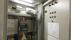
On average, depending on the industry and the size of a plant or factory, a controls engineer could between 20 and 3,000 motor control circuits. That being said, a motor control circuit should be something that controls engineers are familiar with.
What makes up a motor control circuit? And what troubleshooting steps should be taken when a motor control circuit faults? Before expanding on the types of motor control circuits, there are two parts to the motor control circuit—the power circuit, which provides a source, a disconnect switch or breaker, contactor and/or a variable-frequency drive (VFD), along with overload protection, and a motor. Getting rid of power on a drive circuit might require dynamic breaking resistors, depending on the application. The purpose of the power circuit is to drive the motor.
The control circuit in a motor control circuit includes the low-voltage components that incorporate the control transformer, control fuse, emergency stop, stop/start controls, safe torque off sequence, limit switches, selector switches, relays, contactor coils and pilot lights. In context, the control circuit will start, stop and regulate the power circuit to drive the motor.
There are three types of motor control circuits—variable-frequency drives for ac or dc motors, motor starters or soft starters and contactor circuits. Figure 1 shows a power circuit for a VFD with basic controls. We can split the power circuit and the control circuit.The colored wires for the L1, L2 and L3 symbolize a three-phase drive and motor.
If I add buttons for a remote stop start, forward -reverse, then I get a control circuit. The potentiometer symbolizes a remote speed setting, which is common in most applications. Note that a dc drive configuration would be different. Note also the addition of an I/O board or control I/O, and no programmable logic controller (PLC).
Modern drives will allow you to program them and use inputs and outputs from a card on the drive, contingent on how the drive is configured on order and the type of application that is being deployed. I wanted to show a simple motor control circuit to demonstrate the two parts of the motor control circuit.
A motor control circuit with a soft starter is not much different. Note in Figure 2 that there is still a power side and a control side.
A direct online motor control circuit is depicted in Figure 3.
Drawing the two sides of the motor control circuit makes it easy to see what could go wrong. The points of test for a meter are more identifiable: disconnect switch, fuses, contactor, overload relay. Similar to the VFD circuit, electrically, if a motor will not start or move, then it’s best to see where the fault is by locking out and then starting from one end of the circuit and going toward the motor. Or you can start at the motor and go toward the drive.
Finding out the symptoms of the circuit allows further isolation as there are power issues and there are control issues. Power circuit problems show up as a motor not starting, blown fuses or breaker trips, overheating motors, single phasing or low torque. Control circuit problems show up as contactor not energizing, start push button fails, stop button fails, contacts chatter, intermittent operations or failed pilot lights. What else is on the circuit? The motor or the drive.
Motors demonstrate illness by overheating, making noise, vibrating, burning, drawing a high current or not accelerating. Motors get a little petulant. Variable-frequency drives will show fault codes and have erratic speed control or none. Sometimes the motor will not run, or there will be overcurrent trips, communication errors or unexpected shutdowns. Either way, it’s good to understand the sizing and the configuration of the VFD in relationship to the motor and application. Someone could have put in the wrong motor profile or drive configuration, for example.
Get your subscription to Control Design’s daily newsletter.
Soft starters may also cut out based on sizing because the fault current can be adjustable. There was once a motor starter constantly failing on a startup and commissioning because the manager had the electrician build the pump stand on the fly without drawings, and they copied and pasted sizes from the last job. The commissioning engineer got lucky that the motor matched well enough for the sized starter, and the engineer was able to make adjustments.
When a motor control circuit fails, validate incoming voltage and check all fuses and breakers. Ask what is causing such a high current that the protection is being put into action. Then check control voltage. Are the overload relays on or off, and are they healthy? Can the voltage be followed through the circuit until it disappears—power source to motor via disconnects, drive or motor starter and out to the motor? Validate grounding, as well, since a ground will short a circuit.
Megging a motor is a good response if the motor is suspected to have moisture in the windings, deteriorated insulation, ground faults or contamination from oil, dirt or chemicals. Typically, on startups, the motors should be healthy, but, for brownfield projects or daily troubleshooting, the motors may not be healthy. Also, megohmmeter readings without a history of previous readings may give false indications of deterioration. A megger test should happen in context.
Keep in mind that there are two parts to the motor control circuit—power and control. A simple rule of thumb is: If the contactor isn't pulling in, look at the control circuit; if the contactor is pulling in but the motor isn't running, look at the power circuit or the motor. The same will apply to dc motors, except that a dc motor will have a dc voltage source, armature circuits, field circuits, brushes and electronic drive components for dc compatibility.
The power circuit is faulted if ac input to the dc drive is gone. Check the drive if there are fault codes, warning lights and or the cooling fan is off or on without matching the conditions. Is there a field loss, overvoltage or ground fault? Drive indicators are the motor not starting, the motor stopping unexpectedly or a fault in the drive.
Control symptoms include the drive is powered but the motor won’t turn or the motor runs at one speed and there is no response on speed adjustment. When there is no armature voltage, the drive may be the culprit, as well. Low voltage on the armature or fluctuating voltage is a reflection of drive or control issues. Field loss will cause motor overspeed and drive trips. These can be related to open field wires, failed power supplies or loose wiring. Brushes and commutator problems are related to excessive sparking, motor surging, reduced torque and loss of speed control that could be indicative of uneven wear (Table 1).
Again, even on dc motors, apply the rule of thumb: If the contactor isn't pulling in, look at the control circuit; if the contactor is pulling in but the motor isn't running, look at the power circuit or the motor.
About the Author
 Tobey Strauch
Arconic Davenport
Tobey Strauch is currently managing brownfield installations for controls upgrades at Arconic Davenport. She has previously worked as principal controls engineer and before getting her bachelor’s in electrical engineering, was a telecommunications network technician. She has 20 plus years in automation and controls. She has commissioned systems, programmed PLCs and robots, and SCADAs, as well as managed maintenance crews. She has a broad mix of mechatronics with process control. She enjoys solving problems with Matlab and Simscape. Contact her at [email protected].
 Leaders Logo
Leaders relevant to this article: